Do you have a question about the Cruz Evo Rack E20-126 and is the answer not in the manual?
Provides initial assembly instructions in multiple languages for user guidance.
Ensures all parts are present before starting the assembly process.
Identifies the specific vehicle model to ensure correct part application.
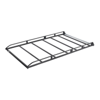
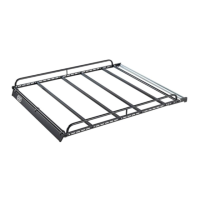
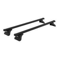
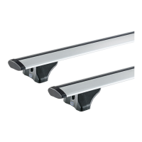
Assembles the main structural components of the roof rack system.
Attaches specific components (A, B, C, D) to the main frame.
Assembles frame components, including part A, into the structure.
Secures components using specified torque values (5 Nm, 6 Nm).
Installs components into the assembled frame structure.
Attaches final components (A, B, C) to the roof rack assembly.
Performs dimensional checks and final attachment with torque specification.
Demonstrates correct placement on the Transit Connect Van model.
Details the installation of part n° 546 with 5 Nm torque.
Details the installation of parts n° 547 and n° 548 with 5 Nm torque.
Illustrates correct placement for Van Double Cab, Kombi, and Tourneo Connect.
Prepares the vehicle's roof rail by inserting specific components.
Details the attachment process with specific dimensions and parts.
Details the installation of part n° 546 with 5 Nm torque.
Details the installation of parts n° 547 and n° 548 with 5 Nm torque.
Illustrates final alignment of the roof rack on the vehicle.
| Maximum Load Capacity | 60 kg |
|---|---|
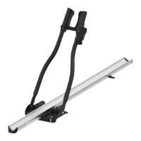
| Number of Bikes | 2 |
| Tiltable | Yes |
| Lockable | Yes |
| Mounting Type | Towbar |
| Load Capacity | 60 kg |
| Weight | 15 kg |
| Color | Black |
| Compatibility | Universal |
| Material | Steel |