31
System Power Supply and Battery
DualCom requires a supply of 13-13.8 volts DC at 75mA in standby and 150mA
when activated.
The installer must ensure that the Alarm System power supply(s) is rated to
provide adequate power for this apparatus and for any other apparatus draw-
ing power from the Alarm System power supply(s).
Only power supplies conforming to EN60950, EN41003 or International Safety
Standards and carrying the CE mark should be used with this apparatus.
The Power Supplies’ battery must be suitable to support operation for the speci-
fied time. Refer to the EN50131 Power Supply standard for the Grade of the
instalation.
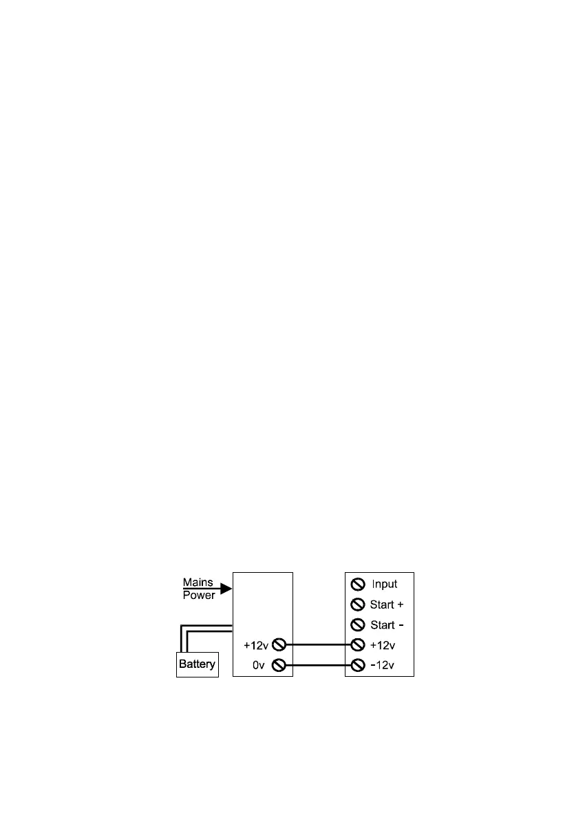
If DualCom receives its power from a Power Supply that is additional to
the alarm system, ensure that the 0 volt connection on the additional
power supply is connected to the 0 volt connection on the alarm system.
If the supply voltage falls to the ‘low battery voltage’ limit, the DualCom will send
a ‘low-battery signal to the ARC. When power is restored above 12.0 volts a test
call (or battery voltage restore signal) will be sent to the ARC. If the supply
voltage continues to fall below 10 volts there will be insufficient power to operate
the unit and the power supply battery may suffer permanent damage.
Note: The ‘Start’ ‘+’ & ‘-’ terminals next to the 8 input terminals are voltage
outputs to aid input triggering only. These terminals are NOT the supply
connector. See Fig 2 & 17.
Power Supply or
Control Panel
DualCom
Fig 17
 Loading...