8
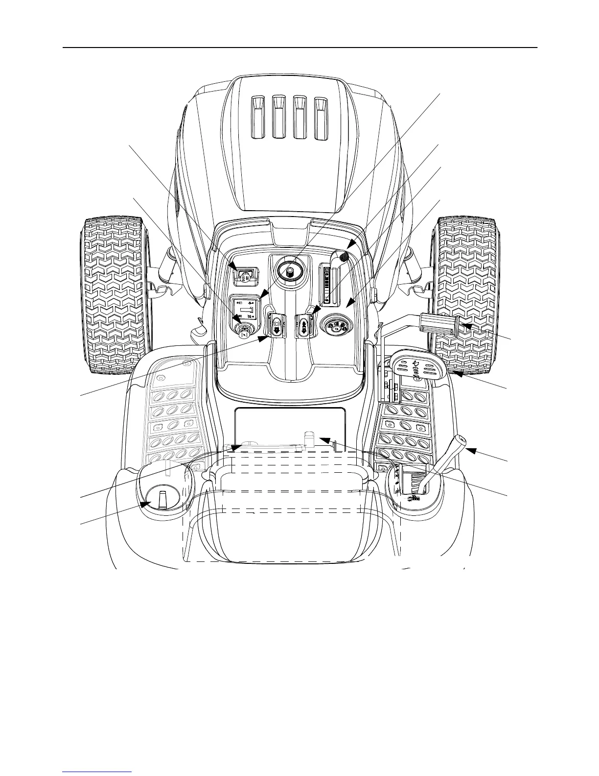
SECTION 7: CONTROLS
Figure 3
A Ignition Switch H Drive Pedal
B Throttle Control Lever I Shift Lever
C Choke Control J Cruise Control Button
D Indicator Monitor/Hour Meter K Seat Adjustment Lever
E Lift Lever L Cup Holder
F PTO (Power Take-Off) Knob M Parking Brake Button
GBrake Pedal
A
C
F
J
M
L
E
H
G
K
NOTE: Steering Wheel not shown for clarity.
1
/
1
0
+
P
B
D
I
NOTE: Any reference in this manual to the RIGHT or LEFT side of the tractor is observed from operator’s position.
 Loading...