The cam stop may be adjusted to allow the imple-
ment to return to a single preset-height. See figure
11
With implement in desired height position,
release cam stop by turning locking knob counter-
clockwise. Turn cam stop until it contacts lift
bracket. Lock cam stop into this position by turn-
ing cam knob clockwise.
The fuel tank filler cap has an air vent. Keep
the vent open at all times to assure proper
flow of the fuel.
NOTE: Gasohol is not approved for use
by the engine manufacturer and
should not be used. The use of
gasohol may damage the engine.
FUEL SHUT-OFF VALVE
The fuel shut-off valve is located below the
gasoline tank.
To turn the fuel on, turn the knob counterclock-
wise to the stop.
To turn the fuel off, turn the knob clockwise until
it is tight.
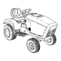
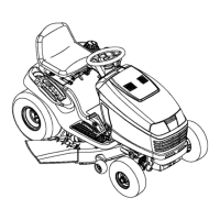
HOOD AND NOISE ISOLATION PANELS
The tractor hood is arranged to swing up and for-
ward for easy access to the engine compartment.
The hood locks automatically when raised. To
lower hood, release latch on left side by gently
pushing hood up to release tension and pull latch
to left. See figure 13. Also, whenever engine
maintenance is required, the noise isolation
panels can be readily removed by removing the
two wing nuts and two washers (one on each side)
and disconnecting the panel spring.
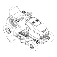
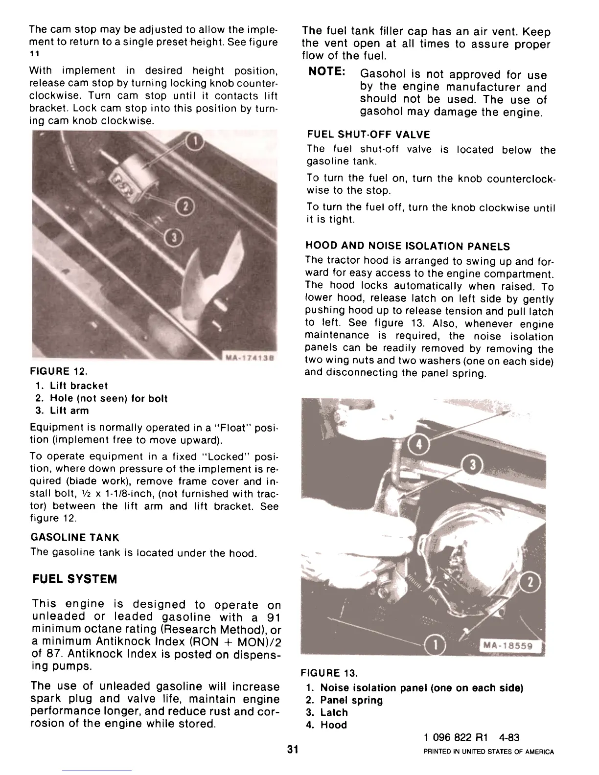
FIGURE 12.
1. Lift bracket
2. Hole (not seen) for bolt
3. Lift arm
Equipment is normally operated in a "Float" posi-
tion (implement free to move upward).To
operate equipment in a fixed "Locked" posi-tion,
where down pressure of the implement is re-
quired (blade work), remove frame cover and in-
stall bolt, 1/2 x 1-1/8-inch, (not furnished with trac-
tor) between the lift arm and lift bracket. See
figure 12.
GASOLINE TANK
The gasoline tank is located under the hood.
FUEL SYSTEM
This engine is designed to operate on
unleaded or leaded gasoline with a 91
minimum octane rating (Research Method), or
a minimum Antiknock Index (RON + MON)/2
of 87. Antiknock Index is posted on dispens-
ing pumps.
The use of unleaded gasoline will increase
spark plug and valve life, maintain engine
performance longer, and reduce rust and cor-
rosion of the engine while stored.
FIGURE 13.
1. Noise isolation panel (one on each side)
2. Panel spring
3. Latch
4. Hood
1 096 822 R1 4-83
PRINTED IN UNITED STATES OF AMERICA
31
 Loading...