The cam stop may be adjusted to allow the imple-
ment to return to a single preset height. See figure
11.
With implement in desired height position,
release cam stop by turning locking knob counter-
clockwise. Turn cam stop until it contacts lift
bracket. Lock cam stop into this position by turn-
ing cam knob clockwise.
FUEL SHUT-OFF VALVE
The fuel shut-off valve is located below the
gasoline tank.
To turn the fuel on, turn the knob counterclock-
wise to the stop.
To turn the fuel off, turn the knob clockwise until
it is tight.
HOOD AND NOISE ISOLATION PANELS
The tractor hood is arranged to swing up and for-
ward for easy access to the engine compartment.
The hood locks automatically when raised. To
lower hood, release latch on left side by gently
pushing hood up to release tension and pull latch
to left. See figure 13. Also, whenever engine
maintenance is required, the noise isolation
panels can be readily removed by removing the
two wing nuts and two washers (one on each side)
and disconnecting the panel spring.
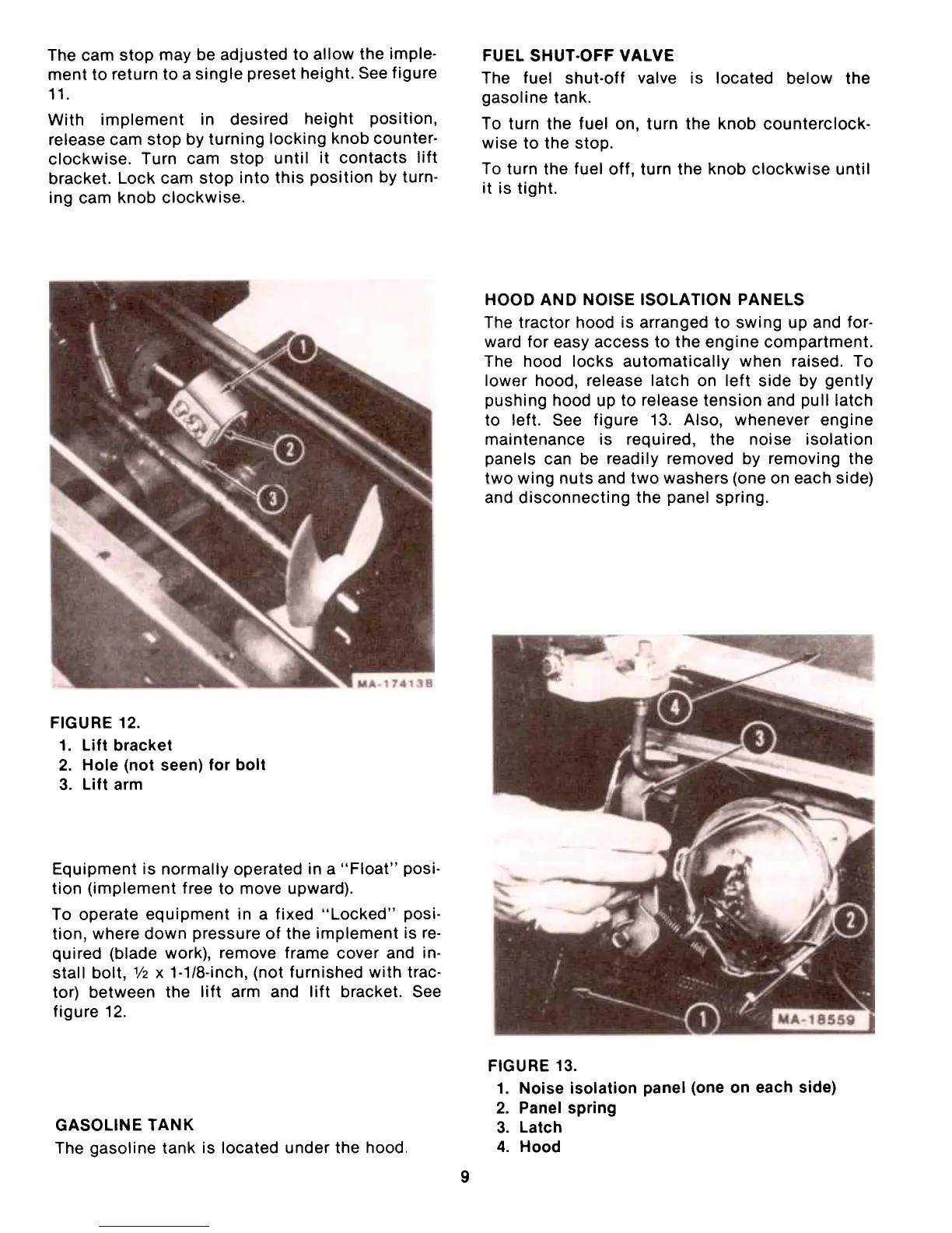
FIGURE 12.
1. Lift bracket
2. Hole (not seen) for bolt
3. Lift arm
Equipment is normally operated in a "Float" posi-
tion (implement free to move upward).
To operate equipment in a fixed "Locked" posi-
tion, where down pressure of the implement is re-
quired (blade work), remove frame cover and in-
stall bolt, 1/2 x 1-1/8-inch, (not furnished with trac-
tor) between the lift arm and lift bracket. See
figure 12.
FIGURE 13.
1. Noise isolation panel (one on each side)
2. Panel spring
3. Latch
4. Hood
GASOLINE TANK
The gasoline tank is located under the hood.
9
 Loading...