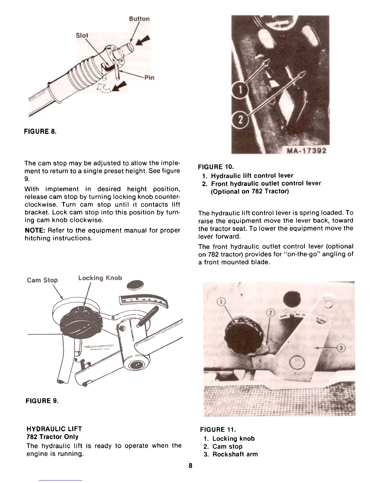
FIGURE 8.
FIGURE 10.
1. Hydraulic lift control lever
2. Front hydraulic outlet control lever
(Optional on 782 Tractor)
The cam stop may be adjusted to allow the imple-
ment to return to a single preset height. See figure9.
With implement in desired height position,
release cam stop by turning locking knob counter-
clockwise. Turn cam stop until it contacts lift
bracket. Lock cam stop into this position by turn-
ing cam knob clockwise.
NOTE: Refer to the equipment manual for proper
hitching instructions.
The hydraulic lift control lever is spring loaded. To
raise the equipment move the lever back, toward
the tractor seat. To lower the equipment move the
lever forward.
The front hydraulic outlet control lever (optional
on 782 tractor) provides for "on-the-go" angling of
a front mounted blade.
FIGURE 9.
HYDRAULIC liFT
782 Tractor Only
The hydraulic lift is ready to operate when the
engine is running.
FIGURE 11.
1. Locking knob
2. Cam stop
3. Rockshaft arm
8
 Loading...