Tractor Set-Up
Moving the Tractor Manually
Your tractor’s transmission is equipped with a hydrostatic relief
valve for occasions when it is necessary to move the tractor
manually. Activating this valve forces the fluid in the transmission
to bypass its normal route, allowing the rear tires to “freewheel.”
To engage the hydrostatic relief valve, proceed as follows:
Locate the hydrostatic bypass rod in the rear of the tractor. 1.
See Figure 3-1.
Pull the hydrostatic bypass rod outward, then down, to lock 2.
it in place.
NOTE: The transmission will NOT engage when the hydrostatic
bypass rod is pulled out. Return the rod to its normal position
prior to operating the tractor.
IMPORTANT: Never attempt to move the tractor manually
without first engaging the hydrostatic relief valve. Doing so will
result in serious damage to the tractor’s transmission.
Shipping Brace Removal
WARNING! Make sure the lawn tractor’s engine is
off, set the parking brake and remove the ignition
key before removing the shipping brace.
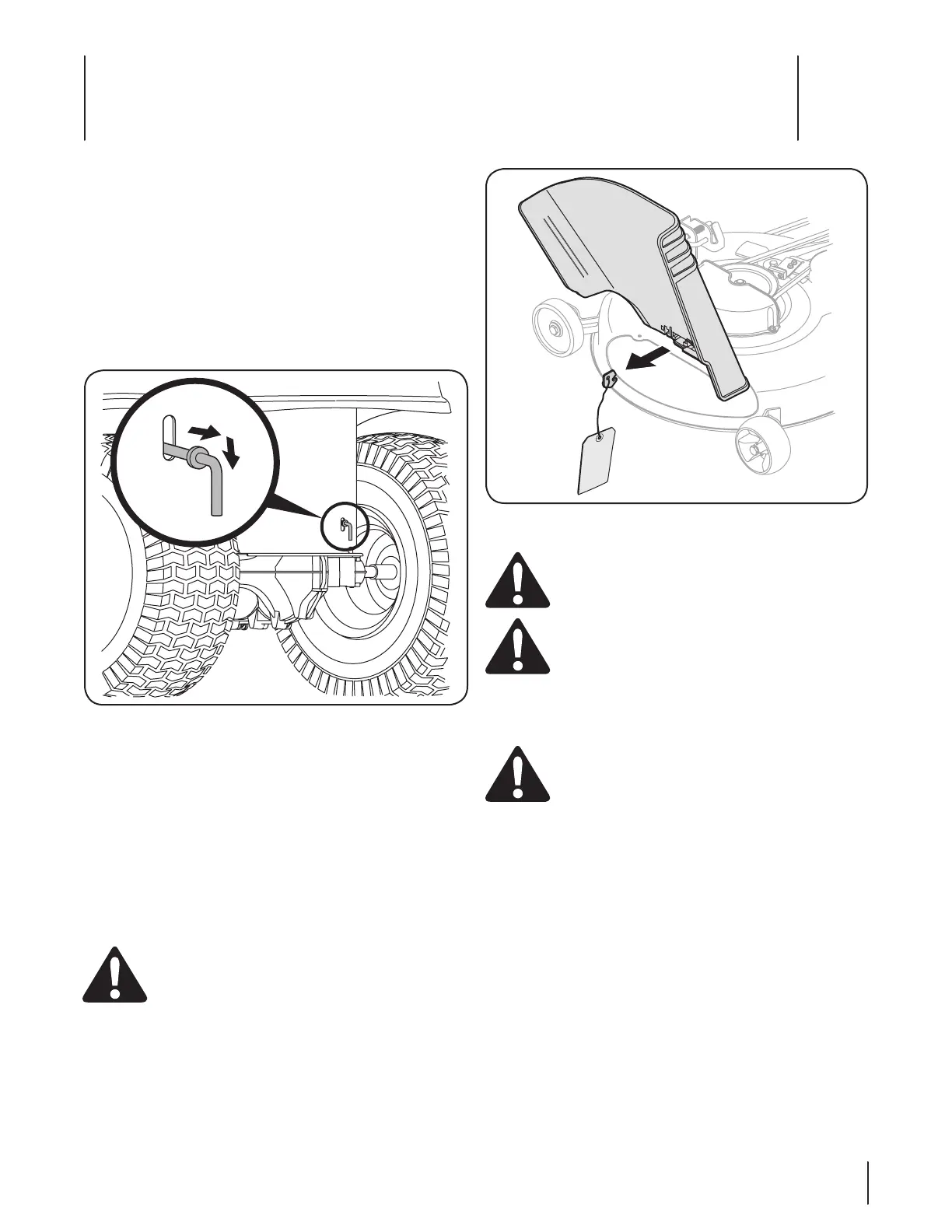
Locate the shipping brace, if present, and warning tag 1.
found on the right side of the cutting deck. See Figure 3-2.
While holding the discharge chute with your left hand, 2.
remove the shipping brace with your right hand by
grasping it between your thumb and index finger and
rotating it clockwise.
WARNING! The shipping brace is used for
packaging purposes only. Remove and discard the
shipping brace before operating your lawn tractor.
WARNING! The mowing deck is capable of
throwing objects. Failure to operate the riding
mower without the discharge cover in the proper
operating position could result in serious personal
injury and/or property damage.
Connecting the Battery Cables
CAUTION: When attaching battery cables, always
connect the POSITIVE (Red) wire to its terminal first,
followed by the NEGATIVE (Black) wire.
For shipping reasons, both battery cables on your equipment
may have been left disconnected from the terminals at the
factory. To connect the battery cables, proceed as follows:
NOTE: The positive battery terminal is marked Pos. (+). The
negative battery terminal is marked Neg. (–).
Remove the plastic cover, if present, from the positive 1.
battery terminal and attach the red cable to the positive
battery terminal (+) with the bolt and hex nut. See Figure
3-3.
Remove the plastic cover, if present, from the negative 2.
battery terminal and attach the black cable to the negative
battery terminal (–) with the bolt and hex nut. See Figure
3-3.
Position the red rubber boot over the positive battery 3.
terminal to help protect it from corrosion.
Figure 3-2
Figure 3-1
Assembly & Set-Up
3
9

 Loading...