adjustments.
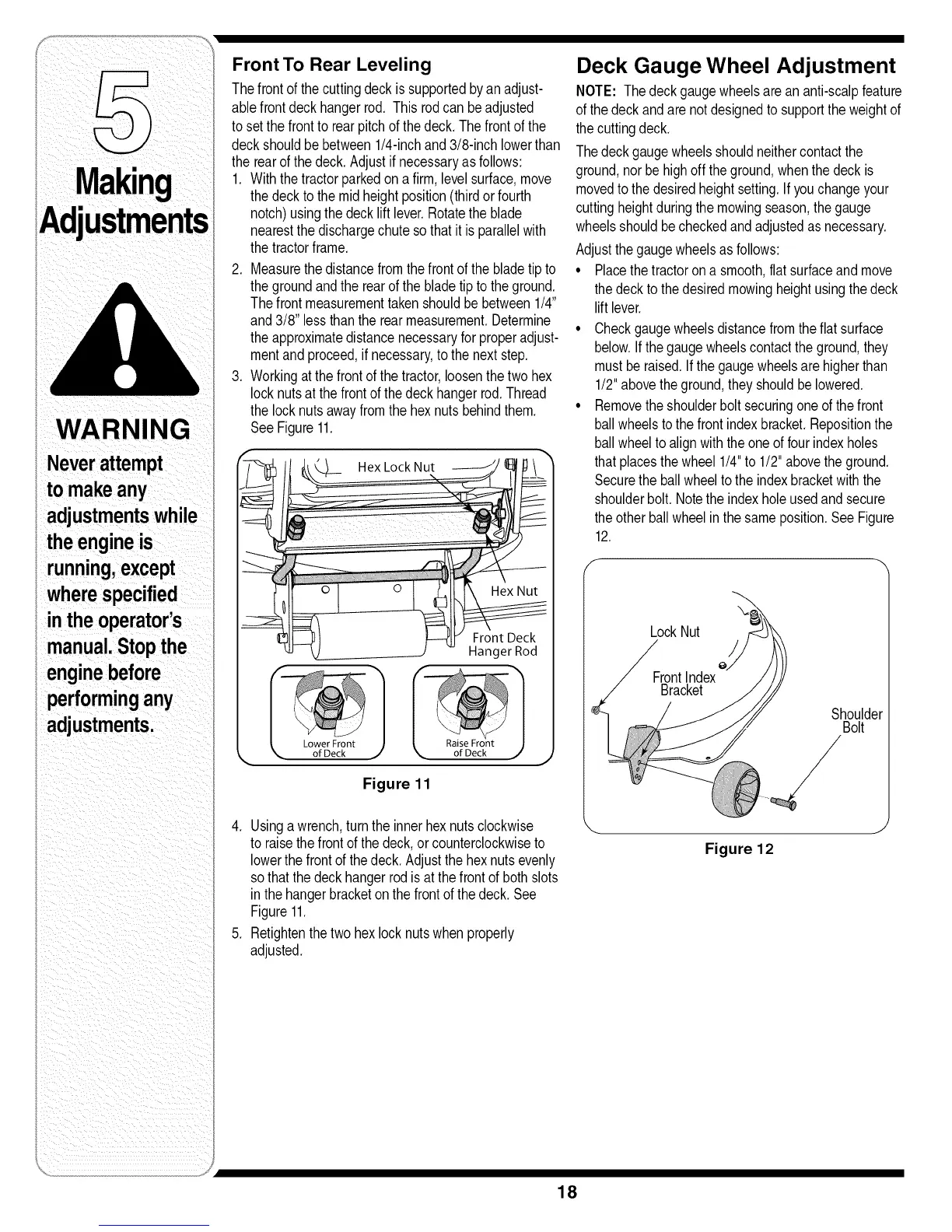
Front To Rear Leveling
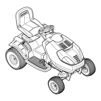
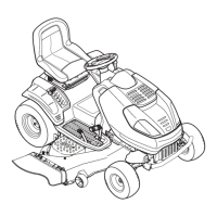
Thefrontofthecuttingdeckis supportedby an adjust-
ablefrontdeckhangerrod. Thisrodcanbeadjusted
tosetthefronttorearpitchofthedeck.Thefrontofthe
deckshouldbe between1/4-inchand3/8-inch lowerthan
therearof the deck.Adjustifnecessaryasfollows:
1. Withthetractorparkedon a firm,levelsurface,move
thedeckto themidheightposition(thirdorfourth
notch)usingthedecklift lever.Rotatetheblade
nearestthedischargechutesothatit isparallelwith
thetractorframe.
2. Measurethedistancefromthefrontof the bladetip to
thegroundandthe rearofthe bladetip to the ground.
Thefrontmeasurementtakenshouldbebetween1/4"
and3/8" lessthantherearmeasurement.Determine
theapproximatedistancenecessaryforproperadjust-
mentand proceed,if necessary,tothe nextstep.
3. Workingatthefrontofthetractor,loosenthe twohex
locknutsatthefrontofthe deckhangerrod.Thread
thelocknutsawayfromthe hexnutsbehindthem.
SeeFigure11.
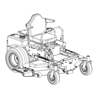
Raise Front
of Deck _ of Deck j
Figure 11
4. Usinga wrench,turntheinnerhexnutsclockwise
toraisethefrontof thedeck,orcounterclockwiseto
lowerthe frontof the deck.Adjustthe hexnutsevenly
sothatthedeckhangerrodisat the frontof bothslots
inthehangerbracketon the frontof thedeck. See
Figure11.
5. Retightenthetwo hexlocknutswhenproperly
adjusted.
Deck Gauge Wheel Adjustment
NOTE: Thedeckgaugewheelsarean anti-scalpfeature
ofthedeckandare notdesignedto supporttheweightof
thecuttingdeck.
Thedeckgaugewheelsshouldneithercontactthe
ground,norbe highoff the ground,whenthe deckis
movedtothedesiredheightsetting.If youchangeyour
cuttingheightduringthe mowingseason,thegauge
wheelsshouldbecheckedandadjustedas necessary.
Adjustthegaugewheelsasfollows:
• Placethe tractorona smooth,flatsurfaceandmove
thedecktothedesiredmowingheightusingthe deck
lift lever.
• Checkgaugewheelsdistancefromtheflat surface
below.Ifthegaugewheelscontactthe ground,they
mustbe raised.Ifthe gaugewheelsarehigherthan
1/2"abovetheground,they shouldbelowered.
• Removethe shoulderboltsecuringone of thefront
ballwheelstothe frontindexbracket.Repositionthe
ballwheelto alignwiththeoneoffourindexholes
thatplacesthewheel1/4"to 1/2"abovethe ground.
Securethe ballwheeltotheindexbracketwiththe
shoulderbolt.Notethe indexholeusedandsecure
theotherballwheelinthe sameposition.SeeFigure
12.
LockNut
FrontIndex
Bracket
Shoulder
Bolt
Figure 12
18

 Loading...