10
OPERATION
I. FUEL CAP
Turn the fuel cap counter clockwise and pull upward to remove. The fuel cap is tethered to the mower
to prevent its loss. Do not attempt to remove the fuel cap from the mower. Fill tank to 1/2” (12.7 mm)
below the bottom of the filler neck, allowing some space in the tank for fuel expansion. Do not overfill
the tank.
Push the fuel cap downward on the fuel tank fill neck and turn clockwise until the cap clicks at least two
times to tighten. Always re-install the fuel cap tightly onto the fuel tank after removing.
WARNING
Never fill the fuel tank when the engine is running. If the engine is hot from recently running,
allow to cool for at least five minutes before refueling. Highly flammable gasoline could
splash onto the engine and cause a fire.
J. FUEL GAUGE IF EQUIPPED
There is a fuel gauge on top of the tank to the left of the operator’s platform.
K. CHOKE KNOB IF EQUIPPED
The choke knob is located on the control panel. Pull the knob out to choke the engine;
push the knob in/down to open the choke. Having the choke in the “ON” position helps
the engine to start during initial start-up. During normal operation the choke should
be “OFF”.
L. THROTTLE CONTROL LEVER
NOTE: When set in a given position, a uniform engine speed will be maintained.
Throttle Control Lever - Push the throttle control lever forward to increase the engine speed. The mower
is designed to operate with the throttle control lever at full throttle (FAST)
when the mower is
being driven and the mower deck is engaged. Pull the throttle control lever rearward to decrease the
engine speed (SLOW) .
M. POWER TAKEOFF PTO ELECTRIC PTO
The PTO switch operates the electric PTO clutch mounted on the bottom of the engine
crankshaft. Pull the switch knob upward to engage the PTO clutch, or push the knob
downward to disengage the clutch.
The PTO switch must be in the “OFF” position when starting the engine.
N. IGNITION SWITCH
WARNING
Never leave a running machine unattended. Always disengage PTO, set parking brake, stop
engine and remove key to prevent unintended starting.
The ignition switch has three positions:
STOP
— The engine and electrical system is turned off.
RUN
— The riding mower electrical system is energized.
START
— The starter motor will turn over the engine. Release the key immediately when the
engine starts, the key will automatically return to “Run” position.
NOTE: To prevent accidental starting and/or battery discharge, remove key from the ignition switch
when mower is not in use.
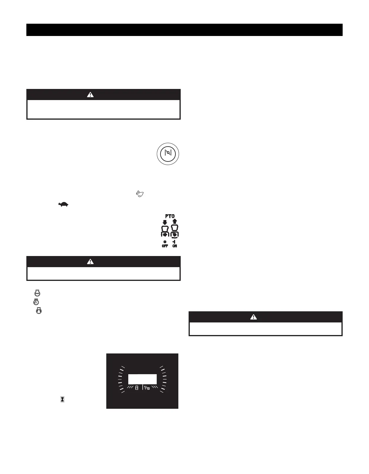
O. HOUR METER & LCD SERVICE MINDER IF EQUIPPED
The LCD service minder will remind the operator
of maintenance intervals for changing the engine
oil, air filter service, low engine oil and low battery
warnings. When the key is rotated out of the STOP
position but is not in the START position, the LCD
service minder & hour meter will briefly display
the battery voltage, followed by the mower’s
accumulated hours.
NOTE: When the ignition key is out of the STOP
position the hourglass
symbol is illuminated/
blinks to indicate it is recording the hours of mower
operation, regardless of whether the engine has
been started.
CHOKE
• Change Oil - The LCD screen will alternate the letters “CHG”, followed by “OIL”, followed by “SOON”,
followed by the meter’s accumulated time. “CHG/OIL/SOON/TIME” will alternate on the display for 7
minutes after the meter reaches 50 hours. This oil service minder interval will occur every 50 hours.
Before the interval expires, change the engine oil as instructed in the Engine Operator’s Manual.
• Low Oil - The LCD screen will alternate the letters “LO” followed by “OIL”, followed by the meter’s
accumulated time, which indicates the engine has low oil pressure. This is common when starting an
engine. The indicator will remain active until the engine sufficiently builds pressure after starting.
If it remains on with the engine at full speed and after a few minutes of operation, stop the mower
immediately and check the engine oil level and add as instructed in the Engine Operator’s Manual. If
the oil level is correct and the indicator persists, contact an authorized service dealer.
NOTE: The low oil pressure function only works if the engine is equipped with an oil pressure switch.
• Low Battery - At startup, the battery voltage will briefly display, then changes to accumulated
hours. The letters “LO” followed by the letters “BATT” will display, followed by the meter’s
accumulated time. “LO/BATT/TIME” is displayed on the LCD when the voltage drops below 11.5 volts.
When this occurs, the battery is in need of a charge or the engine’s charging system is not generating
sufficient amperage. Charge the battery as instructed in the Product Care section of this manual or
have the charging system checked by your local service dealer.
• Air Filter Service - The LCD screen will display the letters “CLN” followed by the letters “AIR”,
followed by “FILT”, followed by the meter’s accumulated time. “CLN/AIR/FILT/TIME” will alternate
on the display for 7 minutes after the meter reaches 25 hours. This air filter service minder time
interval will be every 25 hours. On intervals that are common with oil service, the oil message will be
displayed first followed by the air filter message.
P. ACCESSORY SWITCH/POWER BAGGER ASSIST/12 VOLT ACCESSORIES RECEPTACLES
The receptacles for optional accessories are on the control panel. See the Attachments & Accessories
section for information. The receptacles are for a 12 volt outlet and head light.
Q. HEADLIGHTS NOT SHOWN/IF EQUIPPED
The headlight located in front of the control panel. The headlights are ON whenever the ignition key is
rotated out of the STOP position and OFF when the ignition key is moved to the STOP position.
R. LEG PAD
The leg pad is located in front of the operator’s position to provide a cushion between the operator and
the mower. Refer to the Adjustments section for instructions on adjusting the leg pad position.
S. SUSPENSION ADJUSTMENT RODS IF EQUIPPED
The mower operator’s platform suspension firmness is adjustable. Moving the two adjustment rods to
one of four combinations (insert FIGURE) will provide a firmer or softer operator’s platform suspension.
T. OPERATOR’S PLATFORM
The operator’s platform is at the rear of the mower.
U. TRANSMISSION BYPASS VALVES
The transmission bypass valves are located on the RH and LH Transmission (one for each transmission).
When in use, the two valves open a bypass within the hydrostatic transmissions, which allows the
mower to be pushed short distances by hand. Refer to the Assembly section for additional instructions.
CAUTION
Never tow your mower. Towing the mower with the rear wheels on the ground may cause
severe damage to the hydrostatic transmissions.
V. HYDROSTATIC TRANSMISSION OIL RESERVOIR
The hydrostatic transmission oil reservoir is connected by hoses to the RH and LH transmission
assemblies, and is located behind the access panel in front of the operator’s platform.
NOTE: Prior to the initial operation of the mower, check the hydrostatic transmission oil level. Refer to
Checking the Hydrostatic Transmission Oil Level on page 19.

 Loading...