22
PRODUCT CARE
NOTE: After adjusting the front cruse bar the mower may require tracking adjustment. If necessary refer
to Mower Tracking in this section.
(b)
(a)
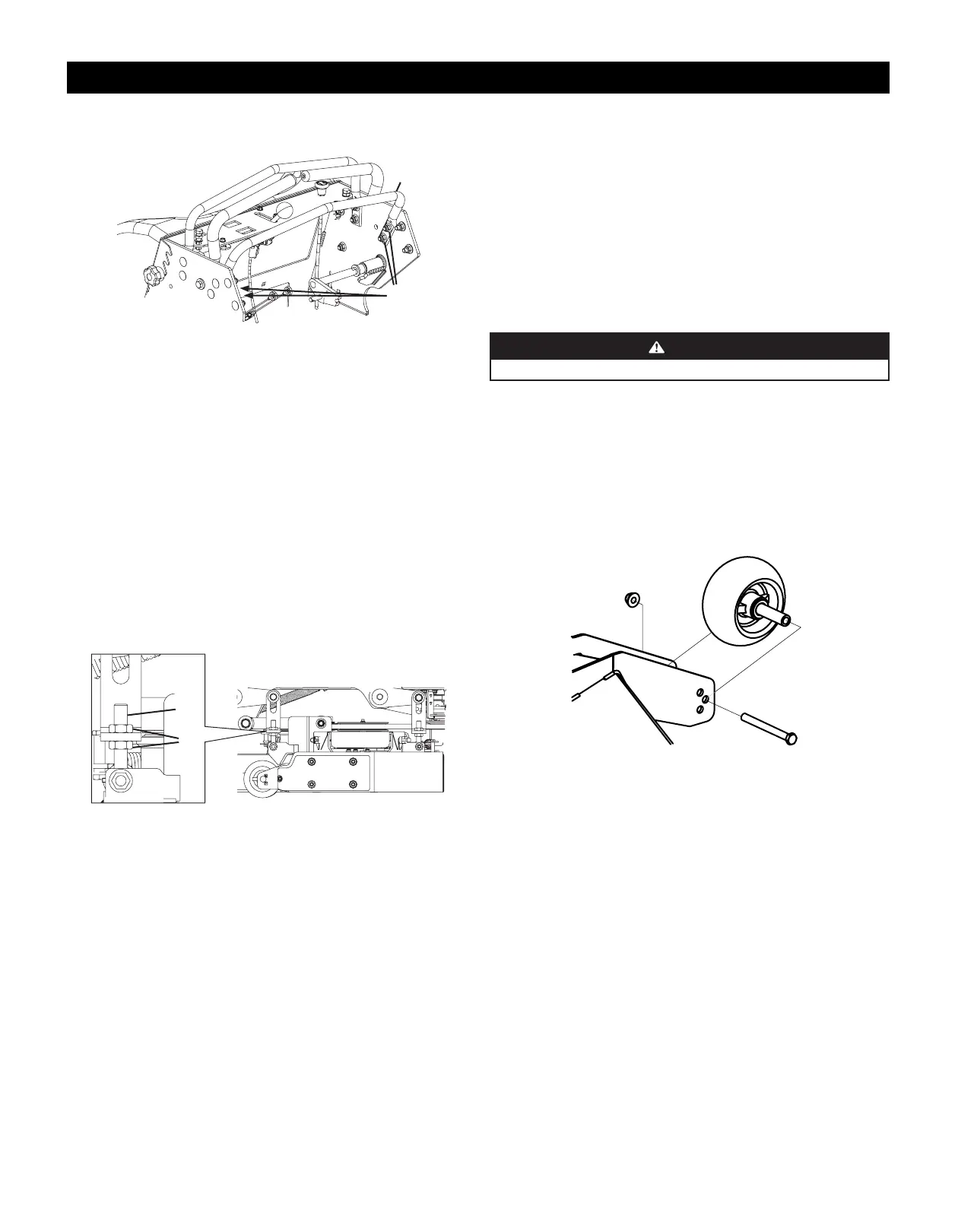
Figure 30
Deck Leveling
NOTE: Check the mower’s tire pressure before performing any deck leveling adjustments. Refer to Tires
for information regarding tire pressure. Always level the deck side-to-side before front to rear.
Side-to-Side Leveling
1. Park the mower on a flat paved surface, engage the parking brake, shut off the engine, remove
the key from the ignition switch, disconnect the spark plug wires, using the deck height index
position the mowing deck into the 4” (10.2 cm) height of cut position (the 4” height of cut position
is recommended in order for one to see and obtain a measurement. Any height of cut position is
acceptable as long as a proper measurement can be taken) and rotate both outside blades so that
they are perpendicular with the mower.
2. Measure the distance from the outside of the left blade tip to the ground and the distance from the
outside of the right blade tip to the ground. Both measurements taken should be equal. If they’re
not, proceed to the next step.
3. Adjust the eyebolt (a) at the left front of the deck so that the blade-to-ground height at the right
outside blade tip matches that of the left outside blade tip. This is done by loosening the jam nuts (b)
on the eyebolt (a) and tightening the upper jam nut (b) to raise the deck and loosening the jam nut
(b) to lower the deck. The right outer blade tip height is fixed by the right, front eyebolt (a) so you
must adjust the left outer tip to match it (Figure 31).
(b)
(a)
Figure 31
4. Once the proper adjustment is made, re-tighten the jam nuts (b).
Front-to-Back Leveling
1. Park the mower on a flat paved surface, engage the parking brake, shut off the engine, remove the
key from the ignition switch, disconnect the spark plug wires, using the deck height index position
the mowing deck into the 4” (10.2 cm) height of cut position (the 4” (10.2 cm) height of cut position
is recommended in order for one to see and obtain a measurement. Any height of cut position is
acceptable as long as a proper measurement can be taken) and rotate both outside blades so that
they are parallel with the mower.
2. Measure the blade-to-ground height at the right rear blade tip. Again be sure to measure at the
blade tip at the rear of the right blade when aligned along the mower center line. The blade-to-
ground height at the rear of the blade tip should be 1⁄8” to 1⁄4” (3.2 to 6.4 mm) higher than the front
tip. This is referred to as blade pitch. The same height difference should be true for the left blade,
measured front and back. The pitch should not exceed 1⁄16” (1.6 mm) if cut height is below 1-1⁄2”
(3.8 cm).
3. Loosen the jam nuts (b) at the rear left and right of the deck eyebolts (a) (Figure 31).
4. Start at the right rear to raise the rear of the deck, tighten the upper jam nut (b) to raise the deck or
loosen the upper jam nut (b) to lower the deck.
5. Adjust the jam nut (b) at the left rear to take the “slack” out of the threaded rod.
6. Tighten both lower jam nuts (b) to secure the deck adjustment.
7. The final adjustment would be to take the “slack” out of the left rear linkage if the rear of the deck
was raised by adjusting the jam nuts (b) on the eyebolt (a). Loosen the jam nuts (b) and tighten the
upper jam nut (b) to remove “slack”.
8. In many cases it will be necessary to adjust deck height using both eyebolt (a) adjustments and pitch
adjustment to achieve the correct blade-to-ground heights. If you remember that the front right
blade tip adjustment is fixed and you level to that height, adjusting the decks will be simplified.
Adjusting the Front Gauge Wheels (if equipped)
WARNING
Keep hands and feet away from the discharge opening of the cutting deck.
The front gauge wheels on the mower deck are an anti-scalp feature, and should not ride on the ground.
The front gauge wheels should be approximately 1⁄4-1⁄2” (6.4 to 12.7 mm) above the ground when the
deck is set in the desired height setting.
Using the deck lift handle, set the deck in the desired height setting, then check the gauge wheel
distance from the ground below. If necessary adjust the front gauge wheels as follows:
1. Visually check the distance between the front gauge wheels and the ground. If the gauge wheels are
near or touching the ground, they should be raised. If more than 1⁄2” (12.7 mm) above the ground,
they should be lowered.
2. Remove the lock nut (a) securing one of the front gauge wheel (b) to the deck. Remove the front
gauge wheel (b), hex screw (c) and spacer (d) (Figure 32).
(a)
(b)
(c)
(d)
(e)
Figure 32
NOTE: There are a pair of front gauge wheels on the nose of the 54” and 60” decks.
3. Insert the hex screw (c) into the one of three index holes in the front gauge wheel bracket (e) that will
give the front gauge wheel (b) a 1⁄4-1⁄2” (6.4 to 12.7 mm) clearance with the ground.
4. Note the index hole of the just adjusted front gauge wheel (b), and adjust the other front gauge
wheel (b) into the respective index hole of the other front gauge wheel bracket (e).
 Loading...