19
PRODUCT CARE
PARKING BRAKE CHECK/ADJUSTMENT 36 INCH DECK ONLY
Check the parking brake engagement after every 50 hours of operation or weekly. The brake wedges
should firmly engage with the tires, pressing down into the tire tread and keep the mower from moving.
Perform the following to check and if necessary, adjust the brake wedge to maintain engagement as the
tire tread wears:
1. Check rear tire air pressure to ensure both rear tires are inflated to the recommended pressure (10-12
psi (69-82.7 kPa) max recommended operating pressure).
2. With the parking break disengaged, measure the gap between the brake wedge (a) and the rear tire
(b) on both sides of the mower. This measurement must be ½ to ¾ (12.7mm - 19mm).
3. If the gap between the break wedge and tire is between ½ and ¾ inches (12.7mm - 19mm) go to
STEP 5. Otherwise go the STEP 4 to adjust brake wedges.
4. If necessary, perform the following to adjust the brake wedges:
e. Disengage the parking brake.
f. Remove the two hex bolts (c) and locknuts (d) securing the brake wedge (a) to the brake wedge
bracket (e).
g. Move the brake wedge up or down to one of five mounting positions (f).
NOTE: Each mounting position will move the brake wedge ⁄ inch (6.4 mm) up or down.
h. Using the two hex bolts and locknuts, secure the brake wedge to the brake wedge bracket.
i. Ensure the gap between the break wedge and tire is between ½ and ¾ inches (12.7mm - 19mm).
10. If necessary repeat STEPS a - d to adjust the remaining brake wedge.
11. Engage the parking brake and ensure the brake wedge engages and presses into the tire on both
sides of the mower. If necessary repeat STEPS 1-6 until the brake wedges should firmly engage with
the tires, pressing down into the tire tread and keep the mower from moving.
12. If the parking brake will not properly engage the tires stop use of mower and see your Cub Cadet
service dealer.
(a)
(b)
½ - ¾ inches (12.7mm - 19mm)
(a)
(c)
(d)
(e)
(f)
Figure 24
USING THE TRANSMISSION BYPASS VALVES
If for any reason the mower will not drive or you wish to move the mower, the two hydrostatic
transmissions are equipped with a bypass valve that will allow you to manually move the mower short
distances.
WARNING
Do not tow the mower, even with the bypass valve open. Serious transmission damage will result
from doing so.
IMPORTANT: The mower is equipped with two hydrostatic transmissions. Each transmission is equipped
with a bypass valve that MUST be opened before manually moving the mower.
IMPORTANT: Unless purging air from the hydrostatic transmission oil system, the bypass valves MUST
be closed before operating the mower.
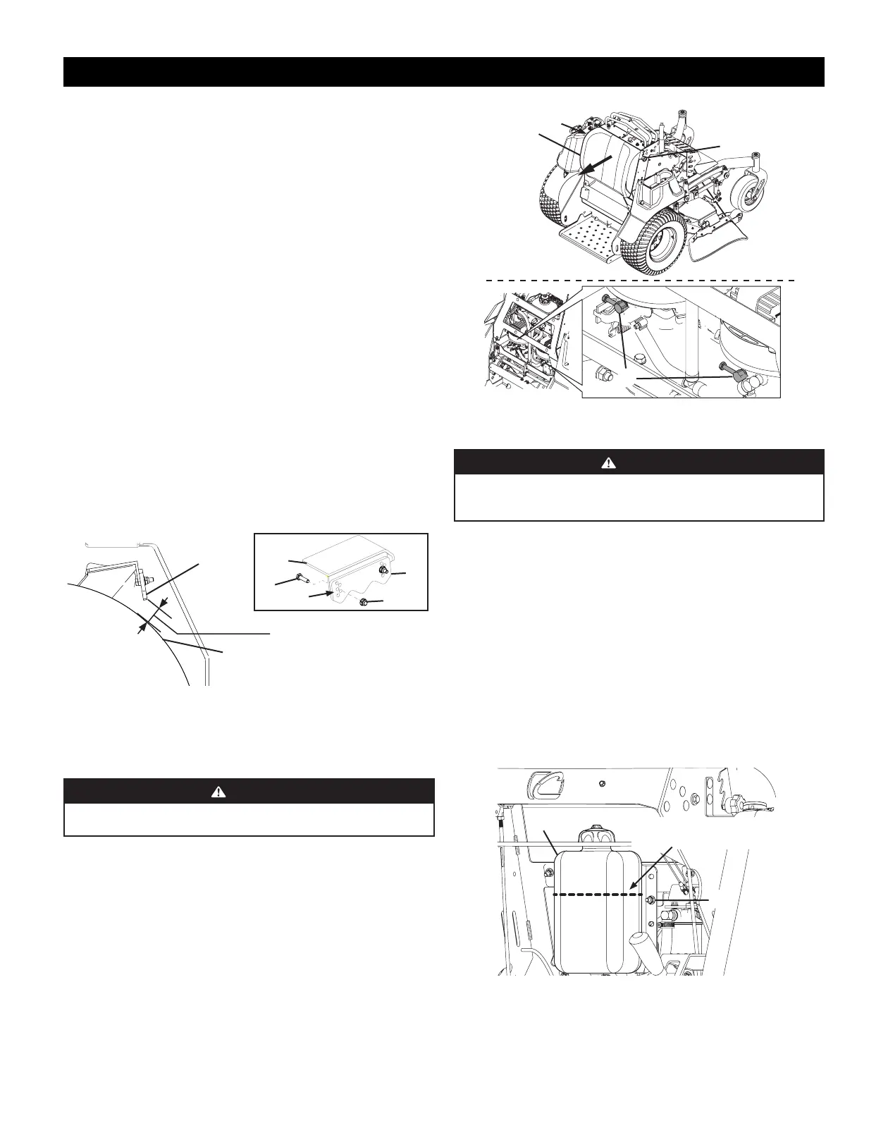
1. Loosen the two star knobs (a) securing the leg pad (b) to the mower (Figure 25).
2. Remove the leg pad from the mower.
3. Remove the rear panel from the mower. Refer to Removing/Installing The Rear Panel on page 7.
IMPORTANT: DO NOT open the bypass valves more than a maximum of two turns.
4. Locate the hydrostatic transmissions and open the two bypass valves (c) a maximum of two turns.
5. Reinstall the rear panel. Refer to Removing/Installing The Rear Panel on page 7.
6. Using the two star knobs, reinstall the leg pad.
7. Reverse STEPS 1-7 to close the two bypass valves.
(a)
(b)
(a)
(c)
Figure 25
HYDROSTATIC TRANSMISSION OIL
WARNING
If the mower has been recently run, the engine, muffler and surrounding metal surfaces will
be hot and can cause burns to the skin. Let the engine cool for at least five minutes. Exercise
caution to avoid burns.
NOTE: This procedure contains the following instructions for checking, changing and adding hydrostatic
transmission oil:
• Checking The Hydrostatic Transmission Oil Level
• Changing The Hydrostatic Transmission Oil
• Adding Hydrostatic Transmission Oil
• Purging Air From The Hydrostatic Transmission
Checking the Hydrostatic Transmission Oil Level
1. Locate the hydrostatic transmission oil reservoir (a) behind the engine under the control panel.
2. Ensure the hydrostatic transmission oil reservoir level is just above the upper reservoir mounting
bolts (b) as shown in Figure 26.
NOTE: The hydrostatic transmission oil level must always stay above the hose fittings on the rear of the
tank, otherwise air may be introduced into the system.
3. If necessary, add hydrostatic transmission oil. Refer to Adding Hydrostatic Transmission Oil in this
procedure.
(a)
Hydrostatic Transmission
Oil Fill Level
(b)
Figure 26
 Loading...