8
SET-UP
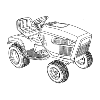
1. Perform one of the following to remove the battery cover:
• Mowers with 48, 54 or 60 Inch Decks - Remove the two thumb screws (a) securing the
battery cover (b) to the right fender. Lift up to remove the battery cover (Figure 4).
• Mowers with 36 Inch Decks - Unhook the rubber strap (c) securing the battery cover (b) to
the battery tray (d). Lift up to remove the battery cover (Figure 4).
(d)
(a)
(b)
(b)
(c)
Figure 4
NOTE: The positive battery terminal is marked POS. (+) (e). The negative battery terminal is marked
NEG. (–) (f).
NOTE: If the positive battery cable (g) is already attached, skip ahead to step 4.
2. Remove the red boot (h), if present, from the positive battery terminal (e) and attach the red cable
(g) to the positive battery terminal (e) with the bolt (i) and hex nut (j).
(j)
(m)
(f)
(e)
(g)
(h)
(i)
(l)
(k)
Figure 5
3. Position the red boot (h) over the positive battery terminal (e) to insulate it and help protect it from
corrosion.
4. Attach the black cable (k) to the negative battery terminal (f) with the bolt (l) and hex nut (m).
5. Reverse STEP 1 to reinstall the battery cover to the left fender.
NOTE: If the battery is put into service after the date shown on top/side of battery, charge the battery
prior to operating the machine.
ADJUSTMENTS
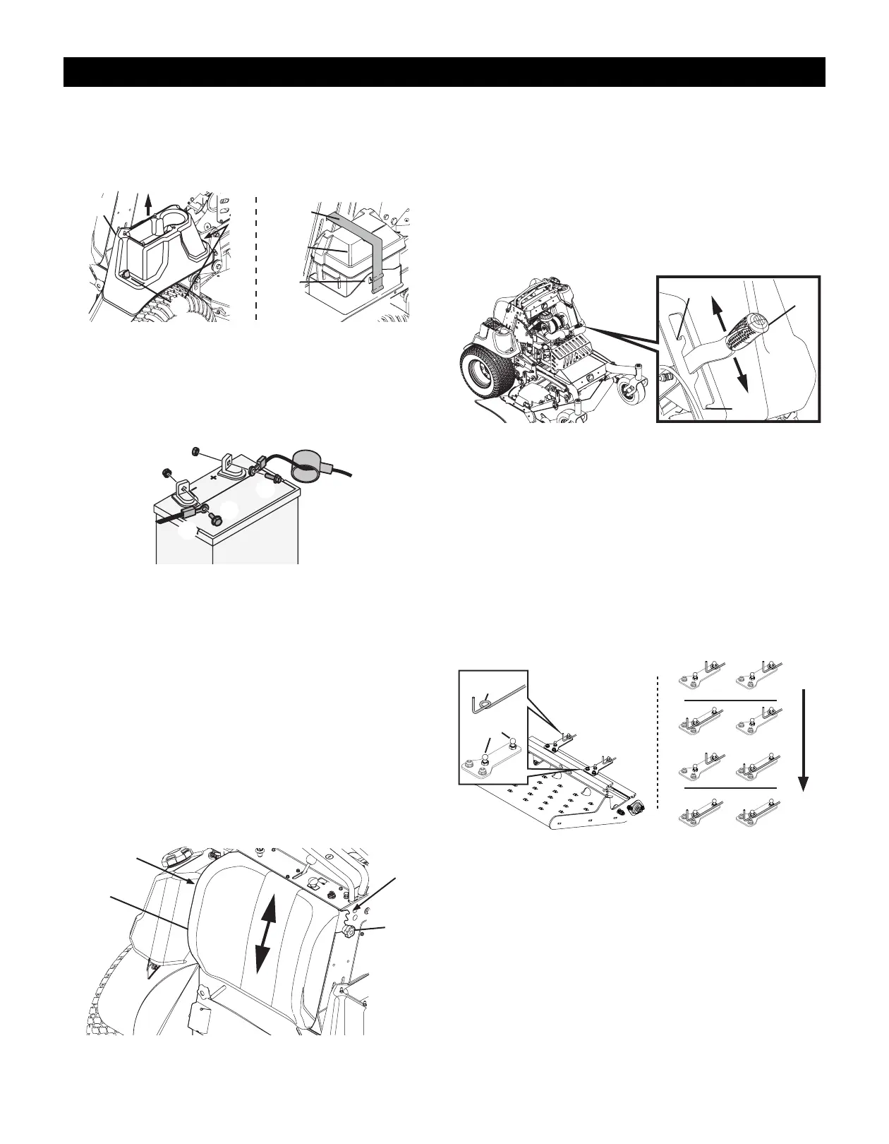
Leg Pad Height
1. Loosen the two star knobs (a) securing the leg pad (b) to the mower (Figure 6).
NOTE: Leg pad for mowers with 48, 54 or 60 inch mower decks shown. Leg pad for mowers with 36
inch mower deck adjusts the same.
2. Remove the leg pad from the mower.
3. Reposition the leg pad into one of three height positions (c).
4. Using the two star knobs, secure the leg pad to the mower.
(a)
(b)
(a)
(c)
Figure 6
Operator’s Platform Suspension
MOWERS WITH 48, 54 OR 60 INCH DECKS
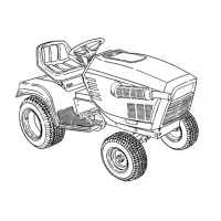
The mower operator’s platform suspension firmness is adjustable. Moving the suspension lever (a) to the
top position (b) provides a firmer suspension. The lower setting (c) provides a softer suspension
(Figure 7).
1. Ensure the mower is unoccupied with the engine off and parking break engaged.
2. Move the suspension lever up and away from the mower.
3. Move the suspension lever to one of three suspension settings.
4. Lower the suspension lever into the suspension setting. Ensure the suspension lever fully engages
the setting before releasing the lever.
(b)
(a)
(c)
Figure 7
Mowers With 36 Inch Decks
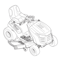
The mower operator’s platform suspension firmness is adjustable. Moving the two adjustment rods to
one of four combinations (Figure 8 Inset) will provide a firmer or softer operator’s platform suspension.
1. Remove the rear panel. Refer to Removing/Installing The Rear Panel, Rear Panel with Quarter turn
latches on page 7.
2. Locate the two adjustment rods (a).
NOTE: Refer to Figure 8 inset to see the stop position locations for the desired suspension firmness.
3. Moving one adjustment rod at a time, slightly pull and lift the adjustment rod off of the ball stud (b).
4. Push or pull the adjustment rod until the loop is over the correct ball stud for the desired suspension
firmness.
5. Lower the adjustment rod down until the loop is fully seated onto the stop post.
6. Repeat STEPS 4 - 5 to reposition the remaining adjustment rod if necessary.
Firm
Soft
or
(a)
(b)
Figure 8

 Loading...