7
SET-UP
IMPORTANT: This mower is shipped without gasoline in the engine. Be certain to service engine with
gasoline and check oil as instructed in the Operation section of the Engine Manual before starting or
operating your mower.
NOTE: References to LEFT, RIGHT, FRONT, and REAR indicate that position on the mower when facing
forward while standing on the operator’s platform.
MOWER PREPARATION
TOOLS NEEDED: Safety glasses, leather gloves, wire cutters.
1. Remove the upper crating material from the shipping pallet, and cut any bands or tie straps securing
the mower to the pallet.
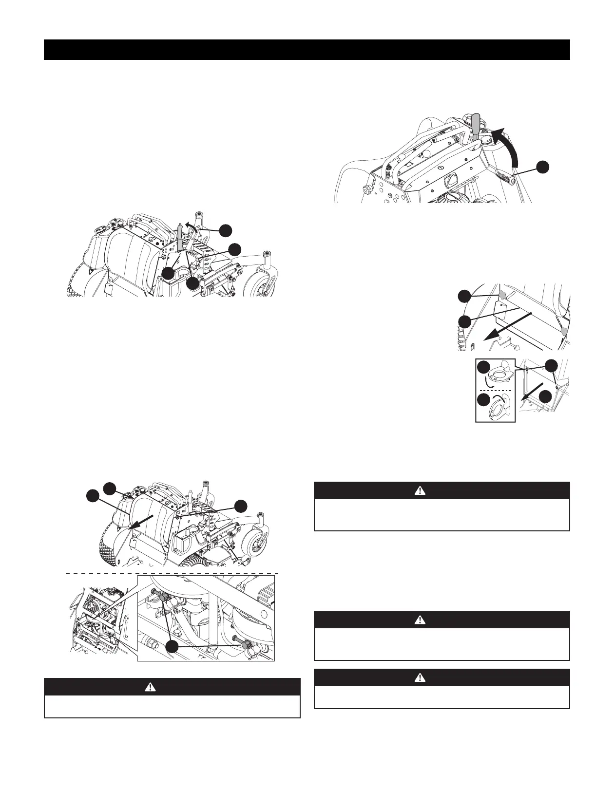
2. Use the deck lift handle (a) to raise the deck to the transport lock position (b) (highest adjustment
setting) and insert the clevis pin (c) into the highest mowing setting (d) to secure the deck lift handle
in place (Figure 1).
d
a
c
b
Figure 1
IMPORTANT: The mower is equipped with two hydrostatic transmissions. Each transmission is equipped
with a bypass valve that MUST be opened before manually moving the mower.
3. Perform the following to open the two hydrostatic transmission bypass valves (Figure 2):
a. Loosen the two star knobs (e) securing the leg pad (f) to the mower.
NOTE: Leg pad for mowers with 48, 56 or 60 inch decks shown. Leg pad for mowers with 36 inch
deck adjusts the same.
b. Remove the leg pad from the mower.
c. Remove the rear panel from the mower. Refer to Removing/Installing The Rear Panel on page
7.
IMPORTANT: DO NOT open the bypass valves more than a maximum of two turns.
d. Locate the hydrostatic transmissions and open the two bypass valves (h) a maximum of two
turns.
e. Reinstall the rear panel. Refer to Removing/Installing The Rear Panel on page 7.
f. Using the two star knobs, reinstall the leg pad.
e
e
f
g
Figure 2
WARNING
Do not tow the mower, even with the bypass valves engaged. Serious transmission damage
will result from doing so.
7. Carefully roll the mower off the shipping pallet.
IMPORTANT: The bypass valves MUST be closed before operating the mower.
8. Reverse STEP 3 to close the two bypass valves.
9. To engage the parking brake, pull back completely on the parking brake lever (j) (Figure 3).
j
Figure 3
10. Cut any wire ties holding the chute deflector up and discard any packing material.
REMOVING/INSTALLING THE REAR PANEL
NOTE: The rear panel is secured to the mower using two star knobs or two quarter turn latches.
IMPORTANT: Ensure the mower is unoccupied with the engine off and parking break engaged before
performing this procedure.
Rear Panel with star knobs
1. Remove the two star knobs (a) securing the rear panel
(b) to the mower.
2. Remove the rear panel from the mower.
3. Reverse STEPS 1 - 2 to install the rear panel.
Rear Panel with Quarter turn latches
1. Lift latch (c) up and rotate the latch one 1/4 turn and align
the latch with the slot in the rear panel. Repeat this step to
the remaining latch.
2. Remove the rear panel (d) from the mower.
3. Reverse STEPS 1 - 2 to install the rear panel.
LUBRICATION & GREASE POINTS
Before operating the mower, refer to the Product Care section of this manual to check the lubrication
and grease points. Grease and lubricate if necessary.
CHECKING TIRE PRESSURE
WARNING
For proper traction and deck leveling the maximum recommended tire pressure is 12 psi.
Equal tire pressure should be maintained at all times. NEVER exceed the Maximum PSI noted
on the tire side wall.
Inflation Pressure
Rear Tires — 10-12 psi (69-82.7 kPa) max recommended operating pressure.
Front Tires — N/A - Front tires are semi pneumatic and do not require inflation.
The tires on your mower may be over-inflated for shipping purposes. Reduce the tire pressure before
operating the mower. Recommended operating tire pressure is 10-12 psi (69-82.7 kPa) for rear tires.
CONNECTING THE BATTERY CABLES
WARNING
California PROPOSITION 65 Battery posts, terminals, and related accessories contain
lead and lead compounds, chemicals known to the State of California to cause cancer and
reproductive harm. Wash hands after handling.
WARNING
When attaching battery cables, always connect the POSITIVE (Red) wire to its terminal first,
followed by the NEGATIVE (Black) wire.
For shipping reasons, both battery cables on your equipment may have been left disconnected from the
terminals at the factory. To connect the battery cables, proceed as follows (Figure 5):
a
b
c
d
1
2

 Loading...