23
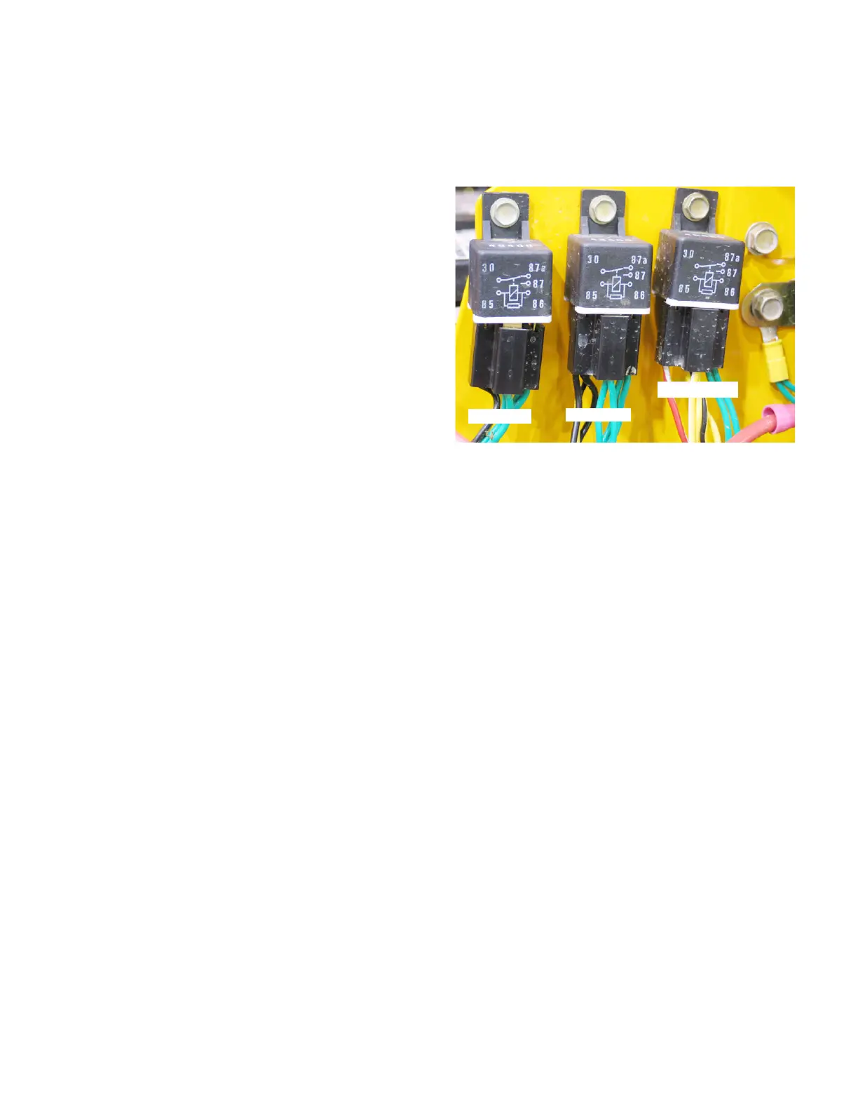
15.7. There are three RELAYS in the electrical system
of the RZT. They are located under the right side
console toward the rear. See Figure 15.7.
-The relays are assessable from under the rear of the
console
-To replace a relay, the console does not need to be
removed.
-When testing by feel a click should be felt when acti-
vated.
-Starting from the left they should be in the order of
SEAT, PTO, and, BRAKE
-The SEAT RELAY should have a consistent ground
(terminal 86) and will receive power (terminal 85) when
the seat switch is activated.
-The PTO RELAY should have a consistent ground
(terminal 86) and will also receive power (terminal 85)
when the seat switch is activated.
-The BRAKE RELAY should have a consistent ground
(terminal 86) and will receive power (terminal 85) when
the brake switch is activated.
15.8. The STARTER SOLENOID is located under the
right console just to the right of the relays.
See Figure 15.8.
- Be certain that there is a good path to ground by mak-
ing sure there is a star washer under the mounting tab
on the starter solenoid.
Figure 15.7
Seat relay
PTO relay
Brake relay
www.mymowerparts.com
K&T Saw Shop 606-678-9623 or 606-561-4983

 Loading...