5
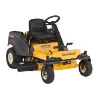
6.6. Mark the lap bar control rod threads near the cle-
vis pin. See Figure 6.6.
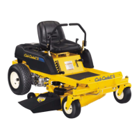
6.7. Remove the hairpin securing the lap bar control
rod to the transmission return assembly.
See Figure 6.7.
Figure 6.6
Lap bar control rod
Ferrule
Figure 6.7
Hair pin
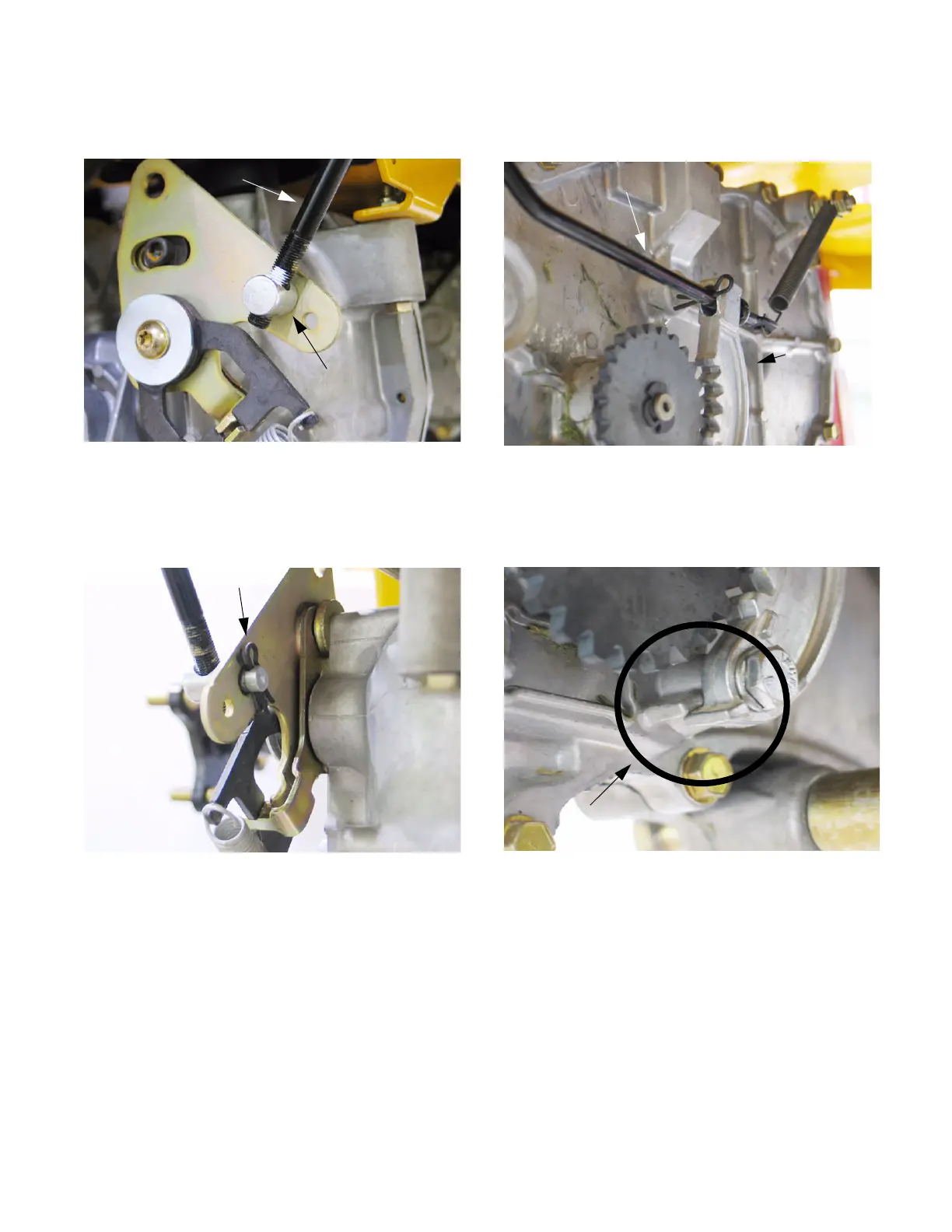
6.8. Disconnect the brake return spring from the
brake arm. See Figure 6.8.
6.9. Remove the bolt securing the brake arm to the
transmission using a 7/16” socket.
See Figure 6.9.
NOTE: A spacer is located between the brake
arm and transmission housing.
NOTE: During installation, the bottom ridge of
the brake arm needs to be below the emboss-
ment on the transmission housing. Improper
installation will prevent the brake from engaging.
6.10. Remove both bolts securing the tubular trans-
mission brace using a 5/8” socket.
NOTE: When installing the brace bolts use loc-
tite 242.
Figure 6.8
Brake arm
Brake rod
Figure 6.9
Note proper installation
www.mymowerparts.com
K&T Saw Shop 606-678-9623 or 606-561-4983
 Loading...