13se c t i O n 4 — as s e M b l y & in s t a l l a t i O n
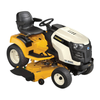
Installing the Discharge Chute
Lift the chute deflector up (1) and place the chute 1.
elbow along the opening on the cutting deck of the
mower.
Slide the two ends of the boot mount, attached to 2.
the discharge chute elbow, under the chute deflector
mounting bracket, beginning with the front portion
of the bracket (2) and rocking the back portion into
place (3). Follow direction of arrows in Figure 4-14.
Note: Make sure the longer end of the boot mount
firmly secures around the bolt head on the chute
mounting bracket. The other end of boot mount
should be securely placed between the chute
mounting bracket and the flange of the deck
opening. See Fig. 4-14.
Note: For the chute elbow to be properly installed,
the bottom edge of the chute elbow must fall below
the toe guard. See the call-out in Fig. 4-14.
Connect chute strap to deck hook. See Fig. 4-15.3.
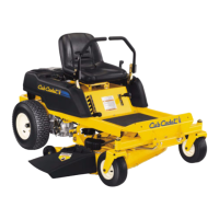
Assembling The Discharge Chute Elbow
Locate the boot mount plate and chute elbow, packaged
with your loose parts in this carton. Attach the boot mount
plate to the chute elbow:
Insert five 710-0751 hex bolts from hardware pack 1.
689-00179 down through the boot mount plate and
Chute Elbow. See Fig. 4-12.
Secure with five 736-0270 bell washers and five 712-2.
3027 flange lock nuts from the same hardware pack.
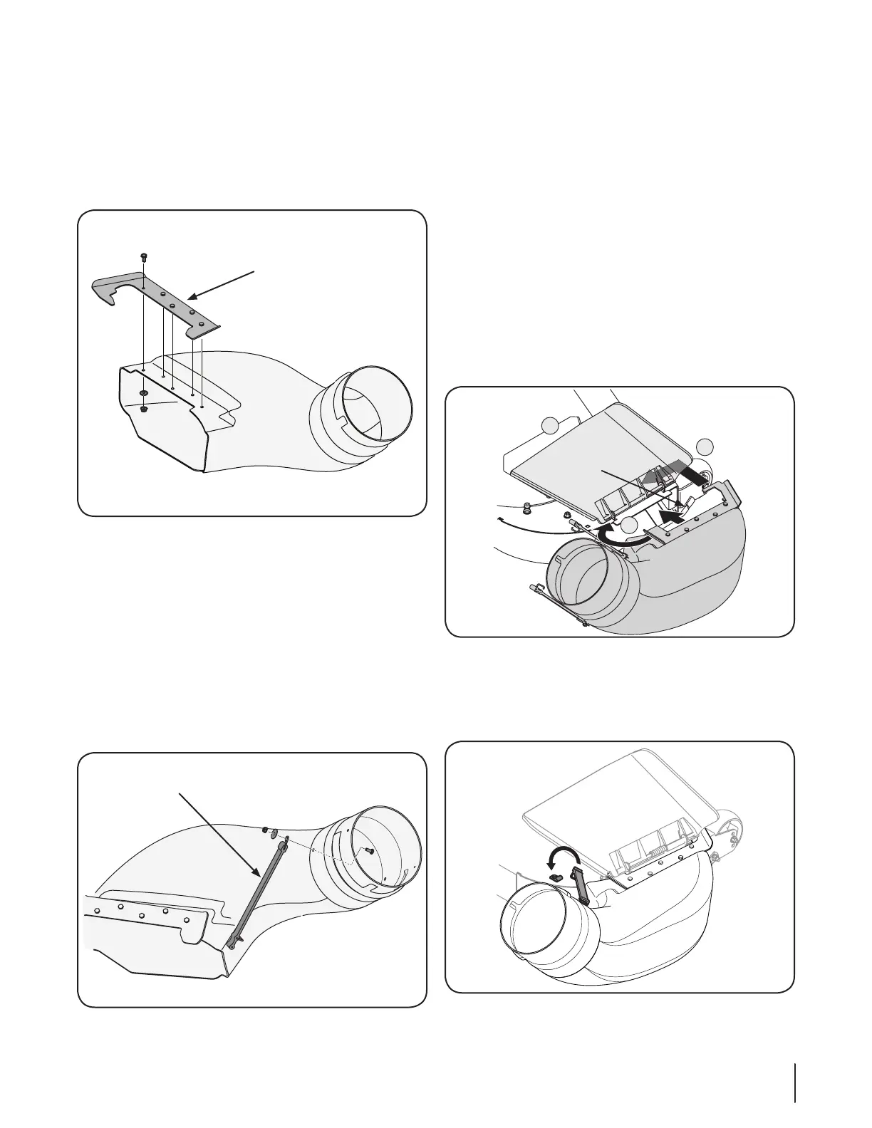
Attach the 723-0476 rubber chute strap to the chute 3.
elbow by inserting a 710-0751 hex head screw from
hardware pack 689-00179, through the chute elbow
from the inside, then through the looped end of the
chute strap, and secure with a 736-3092 flat washer and
712-3027 flange lock nut. See Fig. 4-13.
NOTE: The hook on the chute strap will be facing
down.
Figure 4-12
Figure 4-13
Figure 4-14
Figure 4-15
 Loading...