351804-1 Rev. 100
COM5000-8 TECHNICAL MANUAL
21000044
1638-2001-1
1638-2000-1
L162087
Front
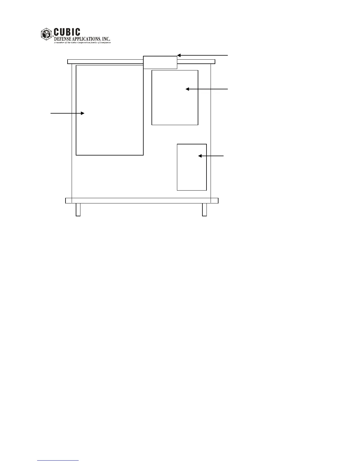
Figure 5.4.3A: SYSTEM CONTROLLER TOP VIEW
5.4.3.1 Driver/Splitter/ALC PCB Maintenance
To gain access to the Driver/Splitter/ALC PCB proceed as follows:
1. Remove the 4 retaining screws that secure the System Controller module to the rack cabinet. Pull the
module slowly out all the way.
2. Remove the 6 screws on the side of the System Controller to remove the top cover. The
Driver/Splitter/ALC PCB is located as shown in figure 5.4.3A.
Adjustments:
The following adjustments should only be performed when a PCB assembly has been repaired in the field.
All PCB's are factory aligned prior to shipment.
Detected RF IN level adjustment:
a) Turn ON the System Controller module. Do not key the system
b) Connect the RF Signal Generator to the System Controller RF INPUT connector, J5. Set the Signal
Generator level to + 16 dBm at a frequency of 2 MHz.