IR
Sensor
P1P2
P3
Pump #1
Power DC Input
Pump #2
Power DC Input
Pump #3
Power DC Input
Pump #2
Pump Connection
Pump #3
Pump Connection
Port#1
Port#2
Port#3
Port#4
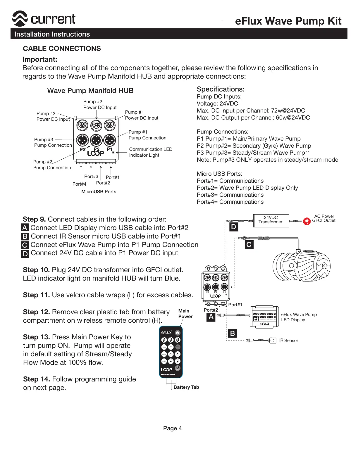
CABLE CONNECTIONS
Important:
Before connecting all of the components together, please review the following specifications in
regards to the Wave Pump Manifold HUB and appropriate connections:
Step 9. Connect cables in the following order:
a. Connect LED Display micro USB cable into Port#2
b. Connect IR Sensor micro USB cable into Port#1
c. Connect eFlux Wave Pump into P1 Pump Connection
d. Connect 24V DC cable into P1 Power DC input
Step 10. Plug 24V DC transformer into GFCI outlet.
LED indicator light on manifold HUB will turn Blue.
Step 11. Use velcro cable wraps (L) for excess cables.
Step 12. Remove clear plastic tab from battery
compartment on wireless remote control (H).
Step 13. Press Main Power Key to
turn pump ON. Pump will operate
in default setting of Stream/Steady
Flow Mode at 100% flow.
Step 14. Follow programming guide
on next page.
Pump #1
Pump Connection
Communication LED
Indicator Light
Specifications:
Pump DC Inputs:
Voltage: 24VDC
Max. DC Input per Channel: 72w@24VDC
Max. DC Output per Channel: 60w@24VDC
Pump Connections:
P1 Pump#1= Main/Primary Wave Pump
P2 Pump#2= Secondary (Gyre) Wave Pump
P3 Pump#3= Steady/Stream Wave Pump**
Note: Pump#3 ONLY operates in steady/stream mode
Micro USB Ports:
Port#1= Communications
Port#2= Wave Pump LED Display Only
Port#3= Communications
Port#4= Communications
Port#1
Port#2
0 1
2
TM
TM
LOCK
Battery Tab
MicroUSB Ports
A
B
C
D
A
B
C
D
Main
Power
 Loading...