Curtis PMC 1209B/1221B/1221C/1231C Manual
9
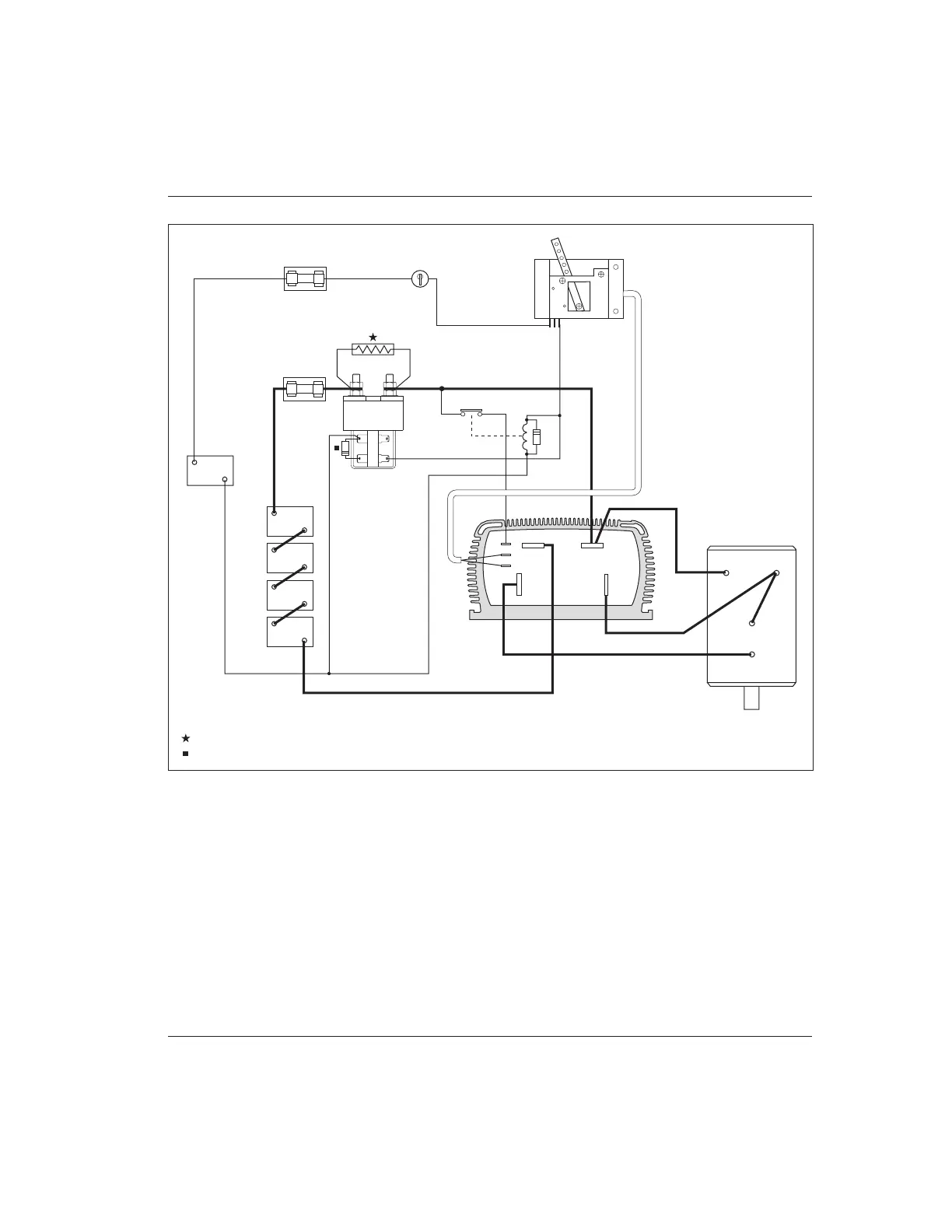
Fig. 8 Typical installation, Curtis PMC 1231C controller.
Contactors should be mounted in a clean, dry location. If such a location is
unavailable, a cover should be used to deflect dirt and water splash.
The precharge resistor and coil suppression diode connected to the main
contactor (and the coil suppression diodes connected to the forward/reverse
contactors in “B” applications) are somewhat delicate components. Care should
be taken to prevent damaging them during installation.
HARDWARE INSTALLATION
CONTROL
WIRING
FUSE
POWER
WIRING
FUSE
KEYSWITCH
POTBOX
MAIN
CONTACTOR
(Albright SW200
shown)
TRACTION BATTERY
B-
B+
PRECHARGE RESISTOR (see Table 1, page 10, for recommended size)
COIL SUPPRESSION DIODE (see text, page 10, for recommended size)
A1
A2
S1
S2
SERIES
MOTOR
12V
AUXILIARY
BATTERY
B+
B-
KSI RELAY
B- B+
A2
M-
COM.
N.C.

 Loading...


