Curtis PMC 1209B/1221B/1221C/1231C Manual
42
APPENDIX A
APPENDIX A
FUNCTIONAL DESCRIPTION
A-1
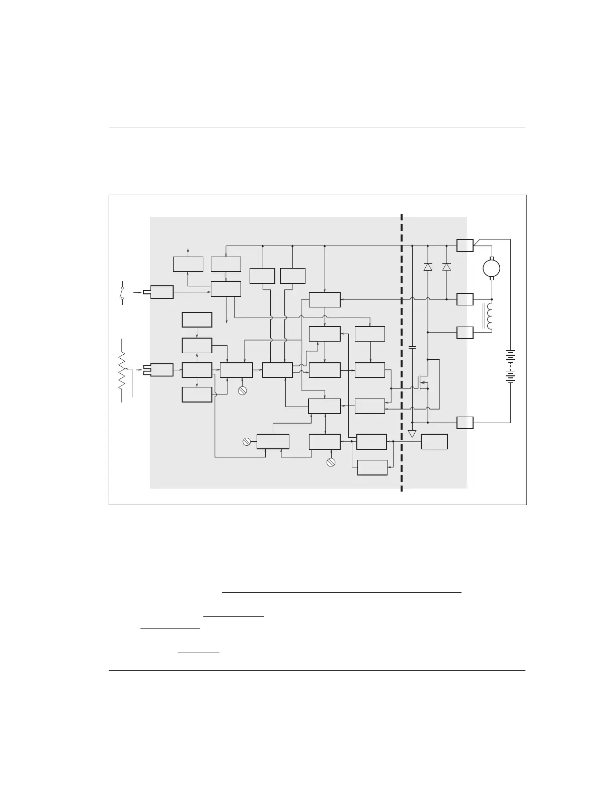
These controllers consist of a POWER SECTION and a LOGIC SECTION, which drives the power section.
POWER SECTION
An array of paralleled power metal oxide semiconductor field effect transistors (MOSFETs) switches pulses
of current from the battery to the motor. During the interval when the MOSFETs are off, the motor current
continues to flow in the freewheel diode, which is actually a number of paralleled fast recovery rectifiers. An
array of filter capacitors connected directly across the battery provides the instantaneous current required by
the power switching circuitry and in this way provides battery ripple current filtering and voltage spike
suppression. The plug diode provides a path for armature current to flow during plug braking.
Fig. A-1 Block diagram, Curtis PMC 1209B/1221B/1221C/1231C controllers.
+14V
REGULATOR
UNDER
VOLTAGE
DETECT
SWITCH
PLUG DIODE
PLUG
DETECT
PULSE
WIDTH
MODULATOR
CURRENT
LIMIT
COMPARATORS
CURRENT
LIMIT
REFERENCE
CURRENT
LIMIT
DISABLE
SHUT
DOWN
GATE
DRIVE
LIMIT
INTEGRATOR
ACCELERATION
CIRCUIT
THROTTLE
INPUT
SCALING
HIGH
PEDAL
DISABLE
START-UP
TIMER
POT
FAULT
OVER
TEMP
UNDER
TEMP
TEMP
SENSE
POWER
SECTION
LOGIC SECTION
B+
A2
M-
B-
FREEWHEEL
DIODE
S1
S2
FIELD
+
FILTER
CAPACITORS
OSCILLATOR
MOSFETs
A1
A2
+
–
ACCELERATION
RATE ADJUST
+14 VOLTS
TO ALL CIRCUITS
ARM
THROTTLE
POT
THROTTLE
INPUT
(SHADED AREA REPRESENTS CONTROLLER)
CURRENT LIMIT
ADJUST
PLUG CURRENT
LIMIT
REFERENCE
PLUG
CURRENT
ADJUST
FIXED PLUGVARIABLE PLUG
+10V
REGULATOR
+10V REFERENCE
KSI
KEYSWITCH
and
INTERLOCKS
OVER
VOLTAGE
DETECT

 Loading...


