Installation
Caution!
Bracket has been designed to remain secured to the
gauge upon proper installation. Once installed
correctly, attempts to remove bracket from gauge
may result in damage to the bracket.
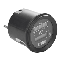
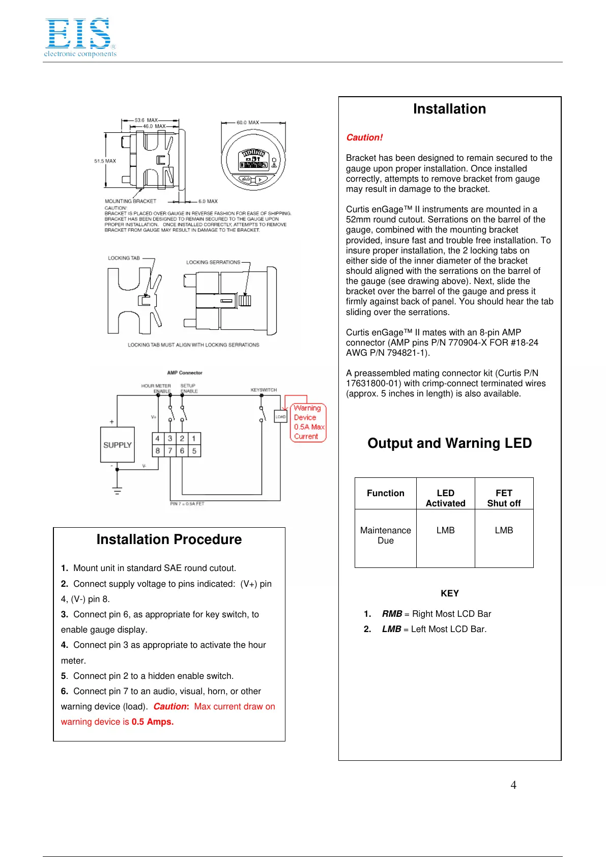
Curtis enGage™ II instruments are mounted in a
52mm round cutout. Serrations on the barrel of the
gauge, combined with the mounting bracket
provided, insure fast and trouble free installation. To
insure proper installation, the 2 locking tabs on
either side of the inner diameter of the bracket
should aligned with the serrations on the barrel of
the gauge (see drawing above). Next, slide the
bracket over the barrel of the gauge and press it
firmly against back of panel. You should hear the tab
sliding over the serrations.
Curtis enGage™ II mates with an 8-pin AMP
connector (AMP pins P/N 770904-X FOR #18-24
AWG P/N 794821-1).
A preassembled mating connector kit (Curtis P/N
17631800-01) with crimp-connect terminated wires
(approx. 5 inches in length) is also available.
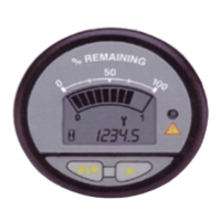
Output and Warning LED
Function
LED
Activated
FET
Shut off
Maintenance
Due
LMB
LMB
KEY
1. RMB = Right Most LCD Bar
2. LMB = Left Most LCD Bar.
Installation Procedure
1. Mount unit in standard SAE round cutout.
2. Connect supply voltage to pins indicated: (V+) pin
4, (V-) pin 8.
3. Connect pin 6, as appropriate for key switch, to
enable gauge display.
4. Connect pin 3 as appropriate to activate the hour
meter.
5. Connect pin 2 to a hidden enable switch.
6. Connect pin 7 to an audio, visual, horn, or other
warning device (load). Caution: Max current draw on
warning device is 0.5 Amps.
4
 Loading...