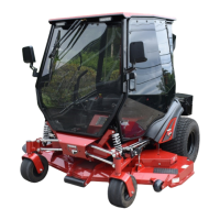
CAB INSTALLATION
14 of 35
Fig. 5.5a (Remove Rear Bolts)
Fig. 5.5b (Remove Lag Screws)
Fig. 5.8 (Install Rear Bolts)
Remove
Inside Cab
Install
Install
Fig. 5.9 (Install Floorboard Bolts)
M8
M8 on
60”
5.5 See figures 5.5a and b. Put tension on the lifting
strap with the overhead hoist. Remove and
discard the 4 bolts holding the rear of the cab
down to the shipping bracket (located inside the
cab) as well as the 4 lag screws holding the
floorboards to the pallet.
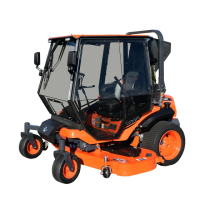
5.6 With assistance, lift the cabin and position over the
vehicle. Be sure to support the A/C compressor
so that it never hangs from the hoses.
5.7 Lower the cabin slowly onto the vehicle being
careful to not scratch the fenders with the rear
edge of the floorboard. The A/C compressor
should pass to the inside of the ROPS and end up
on the left side of the engine.
5.8 See fig. 5.8. Fasten the rear of the cabin to the
ROPS mounts using the following hardware.
Leave loose at this time.
Hardware Used Qty
5/16-18 x 1-3/4 Hex Head Bolt 4
5/16-18 Flange Nut 4
5.9 See fig. 5.9. Fasten the cab to the floor of the
tractor using the following hardware. Note: On 60”
tractors, use 6 M8 bolts. On 72” tractors, only
install 4 M8 bolts and leave additional slot open.
Hardware Used Qty
M8x1.25x40mm Button Head Bolt 4 or 6
5/16x1-1/4” Steel Fender Washers 4 or 6
1/4-20x1” Button Head Bolt 6
1/4x1” Steel Fender Washers 6
1/4-20 Flange Nut 6
5.10 Tighten all floorboard bolts and rear cabin bolts at
this time
5.11 Raise ROPS bar and loosely re-install M16 bolts
used to pin it.
 Loading...