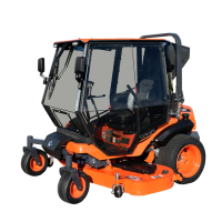
CAB INSTALLATION
8 of 35
1.17 See fig. 1.17. Slip the supplied clip nut onto the
tab rearward of the blade engagement lever.
Hardware Used Qty
#8 Clip Nut 1
1.18 See fig. 1.18. Place the supplied sealing brush
panel over the levers as shown. Secure using the
supplied hardware listed below. Fully tighten at
this time.
Note: The 22mm O.D. x 4.95mm thick washer
(7/8” O.D. x 3/16” thick) is used as a spacer, it’s
placed underneath the brush panel.
Hardware Used Qty
#8 x 5/8” Sheetmetal Screw 1
1/2” O.D. Washer 1
22mm O.D. (.87”) Washer 1
#10-32 x 3/4” Screw 1
#10-32 Lock Nut 1
1.19 See fig. 1.19. Reinstall the large plastic cover,
ignition switch harness, molded throttle lever
handle and blade height adjustment knob along
with its cotter pin.
Reminder: Place the blade engagement lever
into the disengage position at this time.
Leave the drive lever covers off at this point
and continue installing the cab.
Fig. 1.17 (Clip Nut Orientation)
Fig. 1.18 (Brush Panel Orientation)
Clip Nut
#8 Screw &
1/2” O.D.
Washer
22mm O.D. x 4.95mm
Washer
#10-32 Hardware
Fig. 1.19 (Right Side Cover Reinstalled)

 Loading...