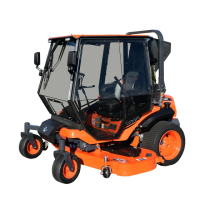
CAB INSTALLATION
7 of 35
1.14 See fig. 1.14. Locate the cotter pin retaining the
blade height adjustment knob. Remove and set
aside the cotter pin and adjustment knob.
1.15 See fig. 1.15. Remove and set aside the three
screws securing the plastic cover to the right side
fender. Pull the molded handle from the throttle
lever and engage the blade lever.
1.16 Carefully lift the cover up and over the throttle and
blade engagement levers. Disconnect the ignition
switch from its harness then place the cover aside.
Fig. 1.14 (Blade Height Adjustment Knob)
Fig. 1.15 (Right Side Cover)
Cotter Pin
Screws
Molded Handle
Removed
Blade lever in the
Engaged Position
Knob

 Loading...