3
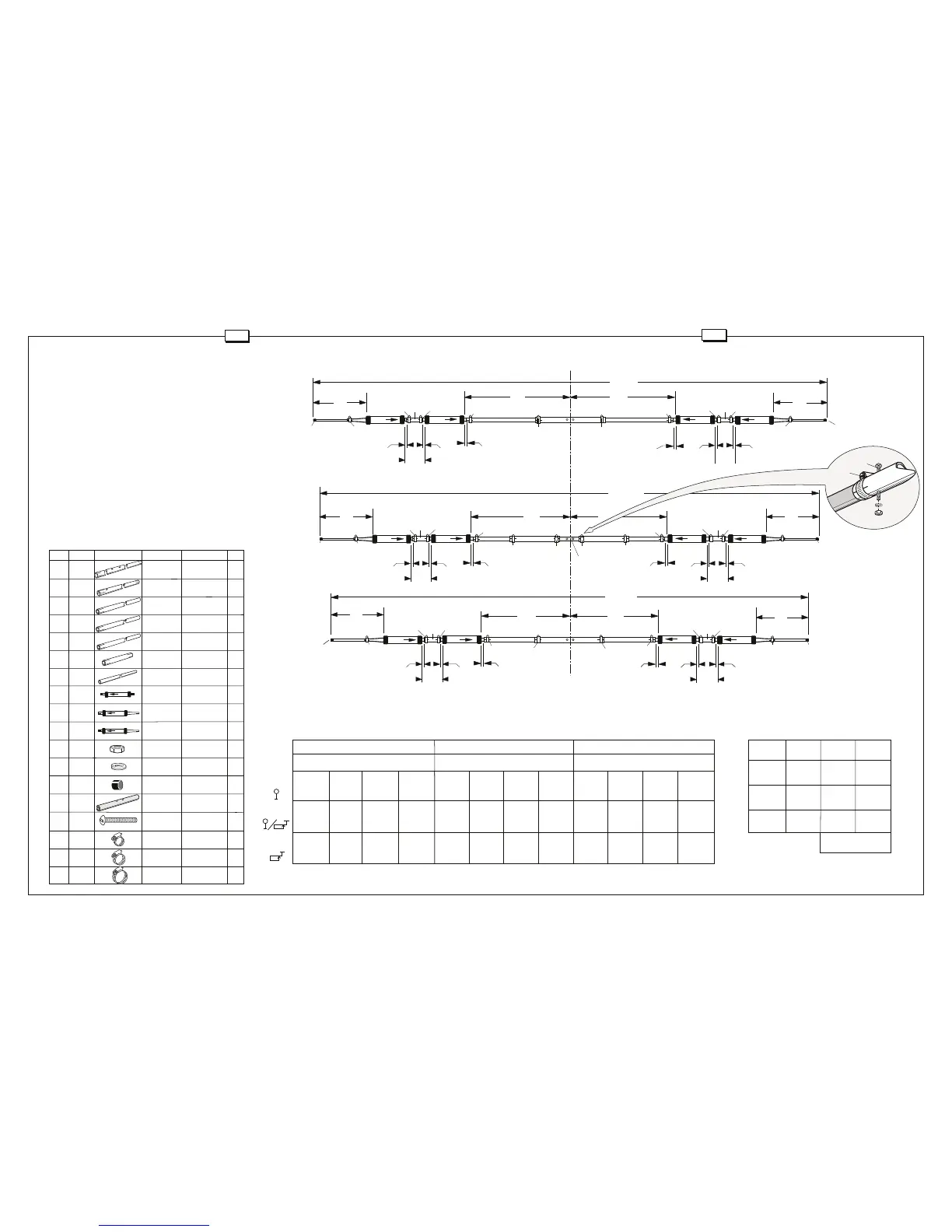
Assemble the elements per Figure B. First place a worm clamp (410)
over the slotted ends of all EC, ED, and EE tubes. Insert the traps (TA)
into the slotted ends of the tubing. Make sure the arrow on the trap faces
the slotted tubing.
Place the worm clamps (411) on both slotted ends of the EB tubes
(element 2). Slide the end with the screw hole of the EB tube onto the
center insulator (96) as shown in Figure C. Align the screw holes in the
tubing with those in the insulator. Place an 8-32 screw (123) through the
tubing and insulator hole and fasten it in place with nuts (11) and washers
(41). Tighten all nuts. Insert the ED tubes into the EB tubes and tighten
the worm clamps.
Place worm clamps (410) at both slotted ends of the EF tubing. Slide
one end onto the TA traps. Attach the TC traps to the other end of tube
EF on elements 1 and 2. Attach the TB traps on element 3. Slide tube
EG into the ends of all elements and secure with worm clamps (409).
Place end caps (53) onto ends. Set dimensions according to the desired
band using Chart 1 and Chart 2 for reference. Tighten all clamps.
4
#2 Element Assembly
Chart 2
EA ALUMINUM 1-1/8" x 72" 2
TUBING (2.9 x 182.9cm)
EB ALUMINUM 1-1/18" x 36" 2
TUBING (2.9 x 91.4cm)
EC ALUMINUM 1" x 67" 2
TUBING (2.5 x 170.2cm)
ED ALUMINUM 1" x 65" 2
TUBING (2.5 x 165.1cm)
EE ALUMINUM 1" x 46-1/2" 2
TUBING (2.5 x 188.1cm)
EF ALUMINUM 1" x 5-1/4" 6
TUBING (2.5 x 13.3cm)
EG ALUMINUM 1/2" x 35-7/8" 6
TUBING (1.3 x 91.1cm)
TA TRAP 10 METER 6
TB DIRECTOR 15 METER 2
TRAP
TC DRIV & REFL 15 METER 4
TRAP
11 010011 HEX #8-32 2
NUT
41 011941 SPLIT #8 2
LOCK WASHER
53 050053 BLK PLASTIC 1/2" 6
CAP (1.3cm)
96 122096 FIBERGLASS 10" 1
INSULATOR (25.4cm)
123 010123 MACHINE #8-32 x 1-1/2" 2
SCREW (3.8 cm)
409 030409 SS WORM 11/16" 6
CLAMP (1.7cm)
410 030410 SS WORM 1" 18
CLAMP (2.5cm)
411 030411 SS WORM 1-3/8" 8
CLAMP (3.5cm)
KEY P/N DISPLAY DESC SIZE QTY
TC
TA
TB
D1
D2
D3
#1
#2
#3
EG
410
EE
EA
411
410
TA
TB
409
53
411
EE
410
TA
TB
410
EF
EF
A3
410
3/8" min
(.95 cm)
B3
C3
TA
TA
TC
TC
3/8" min
(.95 cm)
3/8" min
(.95 cm)
B3
410
3/8" min
(.95 cm)
A3
C3
EB
411
ED
410
EF
EG
411
410
410
409
53
96
A2
3/8" min
(.95 cm)
B2
3/8" min
(.95 cm)
C2
TA
TC
EB
411
ED
410
EF
EG
411
410
410
409
A2
3/8" min
(.95 cm)
3/8" min
(.95 cm)
C2
53
B2
C1
EG
409
EF
410
410
410
EC
EA
411
A1
TA
TC
C1
EG
409
EF
410
410
410
EC
411
A1
53
3/8" min
(.95 cm)
B1
3/8" min
(.95 cm)
3/8" min
(.95 cm)
B1
3/8" min
(.95 cm)
FIGURE B
Chart 1
#1 Reflector
A1 B1 C1 D1 A2 B2 C2 D2 A3 B3 C3 D3
7' 10" 6-1/4" 3' 1" 26' 8-1/2" 6' 9-1/4" 5-3/4" 3' 1-1/2" 24' 7" 6' 2-3/4" 5 -3/4" 2' 11" 23' 1"
238.8 cm 15.9 cm 94.0 cm 814 cm 206.4 m 14.6 cm 95.3 cm 749 cm 190.0 cm 14.6 cm 88.9cm 704 cm
8' 1/2" 6-1/2" 3' 1" 27' 2" 6' 11-1/2" 6" 3' 1-1/2" 25' 6' 5" 6" 2' 11" 23' 6"
245.1 cm 16.5 cm 94.0 cm 828 cm 212.1 cm 15.2 cm 95.3 cm 762 cm 195.6 cm 15.2 cm 88.9 cm 716 cm
8' 2-3/8" 7-3/4" 3' 1-1/2" 27' 9-1/4" 7' 7/8" 7" 3' 1-1/2" 25' 4-3/4" 6' 6-1/8" 7" 2' 11-1/2" 23' 11-1/4"
250 cm 19.7 cm 95.3 cm 883 cm 215.6 cm 17.8 cm 95.3 cm 774 cm 198.4 cm 17.8 cm 90.2 cm 730 cm
#2 Driven Element
#3 Director
53
EG
409
FIGURE C
CW
53
Center
Line
 Loading...