6
FIGURE I
KEY P/N DISPLAY DESC SIZE QTY
11 010011 HEX #8-32 2
NUT
41 011941 LOCK #8 2
WASHER
453 TERMINAL 2
919
403
404
MAST
63
119
118
118
119
119
118
58
58
63
118
119
118
119
118
119
403
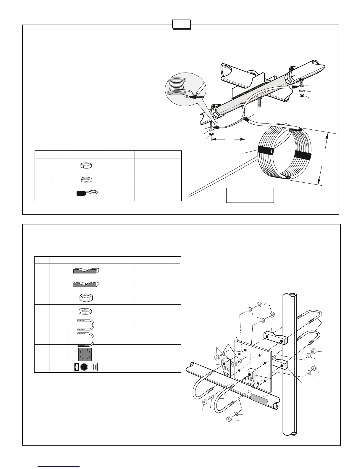
Attach the boom to your mast as shown in Figure I. First attach the
mounting plate (919) to the BA section of the boom using U-bolts
(403), washers (119), nuts (118), and V-blocks (58). Attach the
mounting plate to the mast using the U-bolts (404), V-block (63),
washers (119) and nuts (118). Affix the danger label (326).
KEY P/N DISPLAY DESC SIZE QTY
58 173658 V-BLOCK 3-1/2" 2
(fits 403 U-Bolt) (8.9 cm)
63 170063 V-BLOCK 2" 2
(fits 404 U-Bolt) (5.1 cm)
118 010118 HEX 5/16" 8
NUT (.8 cm)
119 010119 LOCK 5/16" 8
WASHER (.8 cm)
403 010404 U-BOLT 1-5/8" 2
(4.1 cm)
404 010404 U-BOLT 2-1/8 x 3" 2
(5.4 x 7.6 cm)
919 090919 MOUNTING 6" x 6" 1
PLATE (15.2 x 15.2 cm)
326 290326 DANGER 1
LABEL
#4 - RF CHOKE
A feedline should be prepared as shown in Figure H using the
solder terminals (453) provided. A 1:1 balun may be installed
at the feedpoint but it is not required. We recommend using
an RF choke made from 8 turns of RG8/U coaxial cable with
6 inch (15.3 cm) diameter as shown here.
Important
-
Do not
use foam dielectric coax for your RF Choke because when the
coax is wound in a coil the center conductor may migrate away
from the center and detune your choke.
Attach the RF choke
to the driven element using washers (41) and nuts (11). Be
sure to tape and seal the feedline against water at the point
where the center dielectric and braid separate. Tape the
feedline, between the feedpoint and the RF choke, to the boom.
Tape the RF choke to the mast. If you plan to install the antenna
in a salty or corrosive environment, you may want to consider
coating all elements with a clear marine varnish or its equivalent
after it is assembled.
#5 - BOOM TO MAST ASSEMBLY
FIGURE H
BOOM
453
453
6"
(15.2 cm)
4"
(10.16 cm)
41
8 Turns
11
41
11
Electrical
Tape
Warning: Do not use foam
dielectic coax cable.
Electrical
Tape
326
A3S
 Loading...