Verify all parts are present by using the X7 Master Parts List. Check off each part when it is counted. There are extra parts intentionally shipped
with this antenna. Place common hardware in temporary containers for ease of assembly. Note all hardware is Stainless Steel.
Part No. Description Metric Equivalent Quantity
014597 #8-32 x 3" Stainless Steel Machine Screw . . . . . . . . . . . . . . . . . . . . . . . #8 x 7.6 cm 2 ____
X79FS 1/2" Tinned Copper Braid 6" Long with Lugs . . . . . . . . . . . . . . . . . . . 1.2 cm x 15 cm 2 ____
010011 #8-32 Stainless Steel Nut . . . . . . . . . . . . . . . . . . . . . . . . . . . . . . . . . . . . . . . . . . . . . . 8 ____
010082 1/4-20 x 1" Grade V Hex Bolt . . . . . . . . . . . . . . . . . . . . . . . . . . 0.6 cm - 20 x 2.5 cm 48 ____
010085 1/4-20 Stainless Steel Nut . . . . . . . . . . . . . . . . . . . . . . . . . . . . . . . . . . . . . . . . 0.6 cm 15 ____
010120 #8-32 x 2" Stainless Steel Machine Screw . . . . . . . . . . . . . . . . . . . . . . . #8 x 5.1 cm 4 ____
010123 #8-32 x 1 1/2" Stainless Steel Machine Screw . . . . . . . . . . . . . . . . . . . . #8 x 3.8 cm 4 ____
010184 1/4" Stainless Steel Flat Washer . . . . . . . . . . . . . . . . . . . . . . . . . . . . . . . . . . . 0.6 cm 87 ____
010207 3/8" Stainless Steel Flat Washer . . . . . . . . . . . . . . . . . . . . . . . . . . . . . . . . . . . 0.9 cm 4 ____
010208 3/8" Stainless Steel Lock Washer . . . . . . . . . . . . . . . . . . . . . . . . . . . . . . . . . . 0.9 cm 4 ____
1-Verification of Parts
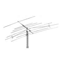
Thank you for your purchase of the Cushcraft X7 Tribander. This antenna is designed and manufactured to give
the best performance and trouble free service. The antenna will perform as specified if the instructions are followed
during assembly and installation. Cushcraft operates a full service Technical Support staff to answer questions
regarding assembly, tuning, parts and just about everything else. Please contact us by phone (603) 627-7877
(8 AM - 5PM Eastern Time), FAX (603) 627-1764, or email techsup@cushcraft.com for prompt service.
WARNING
THIS ANTENNA IS AN ELECTRICAL CONDUCTOR. CONTACT WITH POWER LINES CAN RESULT IN DEATH OR SERIOUS INJURY. DO
NOT INSTALL THIS ANTENNA WHERE THERE IS ANY POSSIBILITY OF CONTACT WITH OR HIGH VOLTAGE ARC-OVER FROM POWER
CABLES OR SERVICE DROPS TO BUILDINGS. THE ANTENNA, SUPPORTING MAST AND/OR TOWER MUST NOT BE CLOSE TO ANY
POWER LINES DURING INSTALLATION, REMOVAL OR IN THE EVENT PART OF THE SYSTEM SHOULD ACCIDENTALLY FALL. FOLLOW
THE GUIDELINES FOR ANTENNA INSTALLATION RECOMMENDED BY THE U.S. CONSUMER PRODUCT SAFETY COMMISSION AND
LISTED IN THE ENCLOSED PAMPHLETS.
Antenna System Planning
Before assembly, take time to review your installation plans for the antenna. Location of the antenna is very important. Surrounding objects such
as trees, power lines, buildings, and other antennas will interact with an HF Yagi. To minimize the effects of surrounding objects, mount the
antenna as high and in the clear as possible. Metallic guy wire within 30 feet of this antenna, broken with strain insulators, will improve performance.
40 Meter Add-On Kit
The X740 40 meter add-on kit is available for the X7. The kit consists of a loaded dipole element that is mounted on the boom section BA between
Elements #2 and #3. The 40 meter element requires a separate coax feed. Contact Cushcraft or your dealer for more information.
YOU MUST INSURE THAT NEITHER PEOPLE OR PETS CAN COME IN CONTACT WITH YOUR ANTENNA WHILE IT IS IN OPERATION.
DEADLY VOLTAGES AND CURRENTS MAY EXIST. ALSO, SINCE THE EFFECTS OF EXPOSURE TO RF ARE NOT FULLY UNDERSTOOD,
LONG TERM EXPOSURE TO INTENSE RF FIELDS IS NOT RECOMMENDED. THERE IS A WARNING STICKER WHICH MUST BE ATTACHED
TO THE BOOM AS SHOWN IN FIGURE 8.
Plan your installation carefully. If you use volunteer helpers be sure that they are qualified to assist you. Make certain that everyone involved
understands that you are in charge and that they must follow your instructions. If you have any doubts at all, employ a professional antenna
installation company to install your antenna.
System Grounding
Direct grounding of the antenna, mast and tower is very important. This serves as protection from lightning strikes and static buildup. A good
electrical connection should be made to one or more ground rods directly at the base of the tower or mast using at least #10 AWG ground wire
and non-corrosive hardware. For details and safety standards, consult the National Electrical Code. A coaxial lightning arrester should be used.
Cushcraft offers several different models such as the LAC series.
Assembly
The assembly procedure for the X7 consists of assembling the following subassemblies.
1) Verification of Parts. 2) Boom Assembly. 3) Element Assembly. 4) Element to Boom Assembly.
5) Feed System Assembly. 6) Boom to Mast Clamp Assembly.
Assembly of the X7 will be easiest if the preceding steps are performed in the given order. For easier tower mounting, some or all of the elements
may be mounted to the boom when the antenna is on the tower. If this option is chosen, the feed system can be attached after the elements
are mounted.
Please read through the entire assembly procedure before beginning.
 Loading...