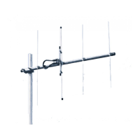
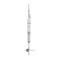
The Cushcraft XM240 is a 40-meter, 2-element Yagi antenna designed to provide optimal performance and reliable service for amateur radio enthusiasts. This antenna system is engineered for efficient communication within the 40-meter band, offering features that enhance signal transmission and reception. Its design focuses on minimizing interaction with surrounding objects, making it suitable for various installation environments, provided proper planning and safety guidelines are followed.
Function Description
The primary function of the XM240 is to facilitate long-distance radio communication on the 40-meter band. As a Yagi antenna, it is a directional antenna, meaning it concentrates radio frequency (RF) energy in a specific direction, enhancing both transmission power and reception sensitivity in that direction. This directional capability allows users to focus their signals towards desired locations, improving signal strength and clarity over greater distances compared to omnidirectional antennas. The 2-element configuration provides a good balance between gain, front-to-back ratio, and physical size, making it a practical choice for many amateur radio operators.
The antenna operates by converting electrical signals from a radio transmitter into electromagnetic waves for propagation through the air, and vice versa for reception. Its elements are precisely tuned to resonate at frequencies within the 40-meter band, ensuring efficient energy transfer. The XM240's design aims to achieve a low Voltage Standing Wave Ratio (VSWR) across its operating bandwidth, which is crucial for efficient power transfer from the transmitter to the antenna and for protecting the radio equipment from reflected power.
Usage Features
The XM240 is designed for straightforward assembly and installation, although careful attention to instructions is emphasized for optimal performance and safety. The assembly process involves several subassemblies: verification of parts, boom assembly, element assembly, X-Hat assembly, feed system assembly, boom-to-mast clamp assembly, and boom truss assembly. Performing these steps in the recommended order simplifies the overall installation.
- Antenna System Planning: Before beginning assembly, users are advised to thoroughly review their installation plans. The location of the antenna is critical; mounting it as high and clear as possible from surrounding objects like trees, power lines, buildings, and other antennas is recommended to minimize interference and maximize performance. If metallic guy wires are used within 30 feet, breaking them with strain insulators can improve performance.
- Safety First: A paramount usage feature is the emphasis on safety. The antenna is an electrical conductor, and contact with power lines can result in severe injury or death. Users are explicitly warned not to install the antenna where there is any possibility of contact or high-voltage arc-over from power cables or service drops. The antenna, mast, and tower must be kept clear of power lines during all phases of installation, removal, or in the event of an accidental fall. Adherence to U.S. Consumer Product Safety Commission guidelines is mandatory.
- RF Exposure Warning: The manual includes a warning about RF exposure, stating that people or pets must not come into contact with the antenna while it is in operation, as deadly voltages and currents may exist. Long-term exposure to intense RF fields is not recommended, and a warning sticker must be attached to the boom as a constant reminder.
- Professional Assistance: For those with any doubts about their ability to safely install the antenna, the manual strongly recommends employing a professional antenna installation company. If volunteer helpers are used, they must be qualified, and the person in charge must ensure all instructions are followed.
- System Grounding: Direct grounding of the antenna, mast, and tower is a critical usage feature for protection against lightning strikes and static buildup. A good electrical connection to one or more ground rods at the base of the tower or mast, using at least #10 AWG ground wire and non-corrosive hardware, is essential. Users should consult the National Electrical Code for detailed safety standards and consider using a coaxial lightning arrester, such as those offered by Cushcraft.
- Boom Assembly: The boom is assembled from multiple aluminum tube sections (BA, BB, BC, BD, BE) using stainless steel hex bolts, lock washers, and lock nuts. The connections are secured to form the main structural support for the elements.
- Element Assembly: The elements are constructed from various aluminum tubes (EA, EB, EC, ED, EF, EG, EH, EJ) and secured with worm clamps. A fiberglass insulator (567) is used at the center of the elements, with #8 screws, lock washers, and nuts securing the EH sections. Element half-length adjustments are crucial for tuning and are determined using a provided chart based on the desired operating frequency.
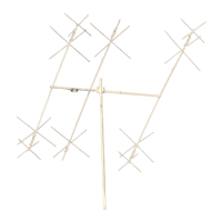
- X-Hat Assembly: The X-Hats, which are part of the loading coils, are assembled using aluminum rods (XHR), aluminum brackets, half washers, SS machine screws, and SS lock nuts. These rods attach to the 40-meter loading coils (LCA) and can be mounted in any position relative to the element or boom.
- Feed System Assembly: The matching network (MN) is attached to the boom, and feed straps (FS) connect the matching network to the driven element screws. Proper hardware, including SS hex bolts, lock washers, and lock nuts, is used for these connections. The feed straps should be positioned away from the U-Channel bracket.
- Boom-to-Mast Clamp Assembly: The antenna is mounted to the mast using aluminum V-blocks, SS flat washers, SS lock washers, SS nuts, and U-bolts. It's important to leave at least 3 feet (91 cm) of mast above the antenna to accommodate the truss assembly.
- Coax Connection: Good quality coax with a PL-259 connector should be attached to the MNXM matching network. A drip-loop should be formed with the coax and secured to the boom. The PL-259 connector must be waterproofed with a good quality sealant after attachment to the matching network.
- Boom Truss Assembly: The boom truss assembly uses Phillystran® cable to guy the boom, providing structural support. The truss bracket is attached to the mast above the boom-to-mast clamp. Turnbuckles are used to adjust cable tension, ensuring the boom ends are level with the center. Cable clamps secure the Phillystran cable.
- Tuning Procedure: The XM240 can be tuned for operation within the 40-meter band by adjusting the length of elements EJ (reflector) and EG (radiator) according to the provided chart, which specifies desired half-lengths for different frequencies.
Maintenance Features
The XM240 is designed for durability and long-term service, with maintenance primarily focused on ensuring structural integrity, electrical connections, and proper tuning.
- Stainless Steel Hardware: The use of stainless steel hardware throughout the antenna system is a key maintenance feature, as it resists corrosion and ensures long-lasting connections, even in challenging outdoor environments. This reduces the need for frequent replacement of fasteners.
- Regular Inspections: While not explicitly detailed as a maintenance schedule, the emphasis on proper assembly and installation implies the need for periodic inspections. Users should regularly check all connections, hardware, and structural components for any signs of loosening, corrosion, or damage. This includes inspecting the boom sections, element connections, X-Hat assemblies, feed system, mast clamp, and truss assembly.
- Cable Clamp and Turnbuckle Checks: The cable clamps securing the Phillystran cable in the boom truss assembly should be checked periodically to ensure they remain tight. Similarly, the turnbuckles used for tensioning the truss cable should be inspected for proper adjustment and security. The manual suggests that a safety wire can be placed through the turnbuckle openings to prevent them from unscrewing, which is a proactive maintenance measure.
- Waterproofing Coax Connections: The instruction to waterproof the PL-259 connector with a good quality sealant is a critical maintenance step to prevent moisture ingress into the coaxial cable and matching network, which could degrade performance or cause damage over time. This seal should be inspected and reapplied as needed.
- Phillystran Cable Durability: The manual notes that Phillystran cable has a minimal amount of stretch over time. This indicates a relatively low-maintenance requirement for the truss system, but occasional re-tensioning via the turnbuckles may be necessary to maintain optimal boom levelness.
- Part Replacement: The detailed parts list provided in the manual serves as a valuable resource for maintenance. In the event of damage or wear, specific parts can be identified and ordered, facilitating repairs and extending the antenna's lifespan. Cushcraft's TECHEXPRESS support service is available for ordering parts and addressing technical questions.
- Warranty Support: Cushcraft offers a one-year limited warranty on the XM240, covering defects in material or workmanship. This provides a safety net for users, ensuring that any manufacturing issues encountered within the first year can be addressed through repair or replacement, provided the antenna has not been subjected to misuse, neglect, accident, or improper installation. This warranty encourages proper handling and installation, which in turn contributes to the antenna's longevity.