3
#1 - ASSEMBLE RADIAL
RINGS
232
232
87
87
428
73
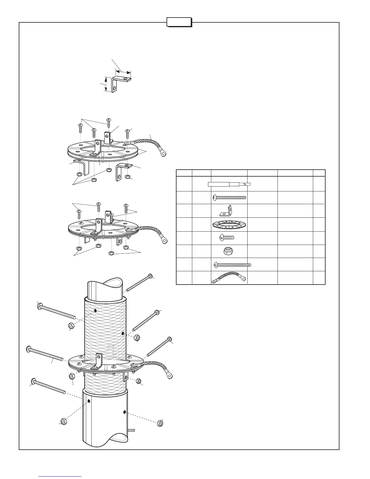
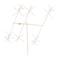
Figures A through D show the steps for radial ring assembly. Refer to the
Radial Ring Subassembly Parts List for the parts required in this step.
Slide the two radial rings (74) onto the base assembly (BA). Note the
orientation of the ring slots. Attach the rings to the base using the radial
ring brackets (73), 2 1/2" screws (232), 1/2" screws (79) and lock nuts
(87). Leave hardware loose until Step #2. Note the proper orientation of
the radial ring brackets in Figure A. Install jumper strap (428) as shown
in Figure D.
NOTE: Do not accidentally use the #10-24 nut in this step.
Insert four 2 1/4" screws (64) into the base assembly (BA) as shown in
Figure D. Secure with nuts (87).
BA BASE 1
ASSEMBLY
64 014764 SS MACHINE #8-32 x 2-1/4” 4
SCREW (5.7 cm)
73 194173 RADIAL RING 4
BRACKET
74 194174 RADIAL RING 2
79 010079 SS MACHINE 8-32 x 1/2" 8
SCREW (1.3 cm)
87 014387 SS LOCK 8-32 14
NUT
232 010232 SS MACHINE 8-32 x 2-1/2" 2
SCREW 6.35 cm)
428 902428 STRAP 1
KEY P/N DISPLAY DESC SIZE
64
64
64
64
87
87
87
87
87
79
87
79
87
87
79
74
73
79
73
FIGURE
D
FIGURE
A
FIGURE
C
FIGURE
B
R6000
Longer dimension
attaches to radial
ring.
Shorter
dimension
attaches to
base.
73
73