3
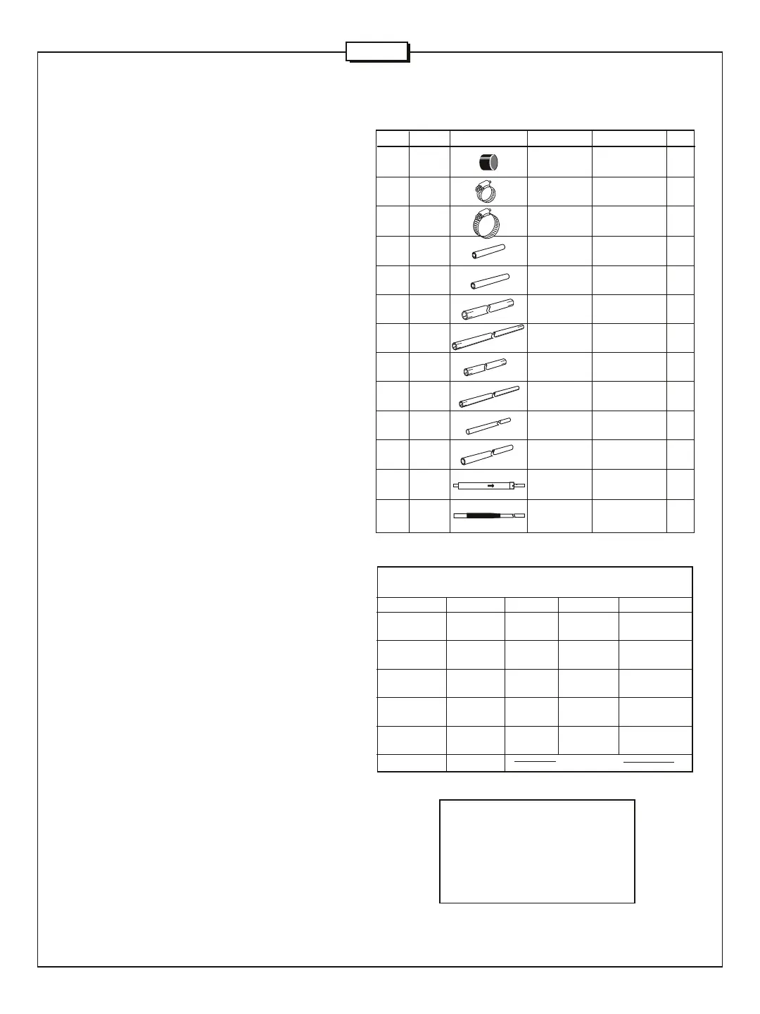
#1 - ASSEMBLE RADIATOR
77 050077 PLASTIC 3/8" 1
CAP (.9 cm)
407 030407 SS WORM 5/8" 2
CLAMP (1.6 cm)
411 030411 SS WORM 1-1/4" 4
CLAMP (3.2)
R80BH ALUM 5/8" x 6-1/2" 1
TUBE (1.6 x 16.5 cm)
R80BI ALUM 5/8" x 7-3/4" 1
TUBE 1.6 x 19.7 cm)
R80BJ ALUM 1" x 12" 1
TUBE (2.2 x 45.7 cm)
R80BK ALUM 7/8" x 18" 1
TUBE (2.2 X 45.7 cm)
R80BL ALUM 7/8" x 6" 1
TUBE (2.2 x 15,2 cm)
R80BM ALUM 3/8" x 36" 1
TUBE (0.9 x 91.4 cm)
R80BN ALUM 1/4" x 43-3/4" 1
ROD (0.6 x 111.1 cm)
R80BO ALUM 3/8" x 15" 1
TUBE (.9 x 38.1 cm)
CT4 40M 1
TRAP
CT5 80M LOADING 1
COIL
KEY P/N DISPLAY DESC SIZE QTY
Dimention Band CW Center SSB
A 10 / 12m 129" 129" 129"
(328 cm) (328 cm) (328 cm)
B 15 / 17m 16" 15" 14"
(41 cm) (38 cm) (36 cm)
C 20 / 30m 17" 15" 14"
(43 cm) (38 cm) (36 cm)
E 40m 22" 13" 8"
(56 cm) (33 cm) (20 cm)
F 80m 2" 2" 2"
(5 cm) (5 cm) (5 cm)
G 80m See Below
Frequency MHz Dimension G
3.525 76" (193 cm)
3.600 64" (163 cm)
3.700 52" (132 cm)
3.800 40" (102 cm)
3.900 23" (58 cm)
3.975 8" (20 cm)*
* Use R80BO tube
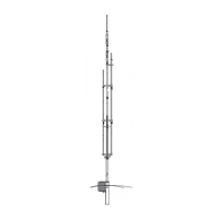
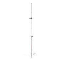
Lower your R7000 antenna or assemble it using the R7000 manual.
Place it horizontally across supports so the couterpoise whips and
capacity hat rods are not damaged.
Place 411 worm clamp on section BC loosely. Loosen worm clamps
at points W,X and Y. Slide CT1 from tubing sections BC and BD1.
Insert R80BH tube into bottom tube of CT1 until it stops against
rivet inside CT1. Slide CT1 into tube BC of the R7000 until it stops
against hardware for capacity hat rods. Tighten worm clamp. Verify
that the length from top of base to bottom of CT1 equals the value
of Dimension A in Chart 1. If you require more length, do not change
the location of CT1. Lengthen exposed tubing sections of tube BB
and BC.
Slide R80BI tube into top of CT1 until it stops against rivet inside of
CT1. Remove both worm clamps (410) from tube BD1 and put aside
for later.
Insert BD1 tube flush into R80BJ tube. Place two 411 worm clamps
from R80 hardware kit on the R80BJ tube (one on each of the slotted
ends). Slide R80BJ assembly two inches onto top end of CT1.
Tighten worm clamp.
Slide CT2 / CT3 assembly into top of R80BJ assembly. Adjust the
length between CT1 and CT2 to match value of Dimension B in
Chart 1. Tighten worm clamp.
NOTE: The next 3 steps depend on whether you will be using CW,
Center or SSB on 40 meters. Choose the appropriate section below.
40m SSB - Loosen worm clamps at points U & V. Remove and
discard BD3 and BG tubes. Place 410 worm clamps on ends of
R80BL. Place R80BL tube on top of CT3. Insert bottom of CT4
into R80BL. Adjust the distance between CT3 and CT4 to match
value of Dimension E in Chart 1. Tighten worm clamps.
40M Center - Loosen worm clamp at point V. Remove and
discard BG tube. Insert bottom of CT4 to match value of Dimension
E in Chart 1. Tighten worm clamps.
40m CW - Loosen worm clamps at points U & V. Remove and
discard BD3 and BG tubes. Place 410 worm clamps on ends of
R80BK. Place R80BK tube on top of CT3. Insert bottom of CT4
to match value of Dimension E in Chart 1. Tighten worm clamps.
Place 411 worm clamp then 410 worm clamp (one of the clamps
from point X or Y) on large slotted tube end of CT5. Leave 411
worm clamp loose for guy bracket attachment in Step #3. Insert
bottom of CT5 onto top of CT4. Tighten worm clamp. Verify that
the length between top of CT4 and bottom of CT5 equals Dimension
F in Chart 1.Note: the next 2 steps depend on whether you will be
using CW, Center or SSB on 80m. Choose appropriate section
below.
NOTE: the next 2 steps depend on whether you will be using
CW/Center or SSB on 80m.
80m SSB - Place 407 worm clamp on top of CT5. Adjust distance
from top of R80BM to top of CT5 to match value of Dimension G
in Chart 1. Tighten worm clamp. For lengths less than 13 inches,
use R80BO tube. Place plastic cap (77) on top of 3/8" tube.
80m Center/ CW - Place 407 worm clamp on top of CT5. Insert
R80BM 2 inches into CT5. Tighten worm clamp. Place 407 worm
clamp on top of R80BM. Insert R80BN into R80BM. Adjust
distance from top of R80BN to top of CT5 to match value of
Dimension G in Chart 1. Tighten worm clamp.
CHART 1
R7000
+
 Loading...