15
ADJUSTMENTS (cont.)
RAISING AND LOWERING HEAD ASSEMBLY
The head assembly consists of the cutterhead, knives, feed rollers, cutterhead guard, and
the motor. Raising and lowering of the head assembly controls the depth of cut on the
planer.
To adjust:
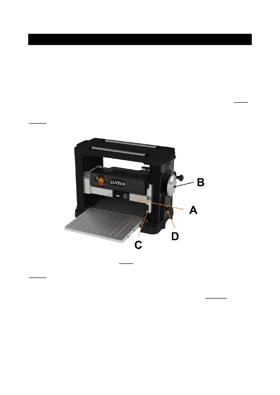
1. To raise the head assembly (A), turn the adjusting handle (B) clockwise. SEE FIG 6.
2. To lower the head assembly, turn the adjusting handle counterclockwise.
NOTE: One revolution of the handle will move the cutterhead up or down approximately
1/16”. You can confirm this by referencing the scale (C) on the front right side of the planer.
FIG 6
NOTE: The Repeat Cut Thickness Indicator (D), located on the bottom right side of the
planer, provides a simple way to preset the finished thickness of a work piece. Rotate the
indicator to the desired finished thickness. Use this feature when thickness planing multiple
work pieces to ensure a uniform thickness of all work pieces. See page 19 for more
information. Do not attempt to lower the cutterhead assembly below the preset level as
damage will occur.