Page 24 of 34
• INJECTORS: Remove the injector brackets and clean the injectors. Do
not tamper with the holes as this will change the power of the fire and
possibly make it dangerous. Once cleaned refit the injectors ensuring
they are sealed to the mixer tube.
• PILOT ASSEMBLY: Clean the pilot assembly ensuring that the pilot
light aeration hole and flame head are clean. Ensure the igniter gap is
set to 4mm. It is recommended to replace the pilot on appliances older
than two years old. Should the pilot assembly need to be replaced, the
original manufacturers parts must be used only. Ensure the pilot draft
shield is fitted.
• MANUAL VALVE: Check for smooth operation of the gas valve. With
the gas turned off check the tightness of the thermocouple connection
into the valve. The gas control valve is factory set and cannot be
adjusted on site. If the valve needs replacement this must be
done at the factory.
• AERATION HOLES: These are factory set to ensure the fire remains
safe. If they become clogged with dust the flame quality will
deteriorate. The holes must be clear at all times. To clean use a
vacuum cleaner as this will ensure that debris does not fall into the
mixer tube and block the injector. Do not Adjust the Aeration.
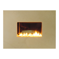
• BURNER: Clean the burner bar to remove any deposits.
• OTHER: Use a vacuum cleaner to remove any dust and debris that
may have built up within the fire box chamber.
• GAS CIRCUIT: Test all joints for leaks if the burner has been
dismantled.
• RE-LIGHT: Light the fire using the method in the instructions and
ensure that the pilot lights constantly and the pilot flame envelopes
the thermocouple. The pilot should hold in for 20 seconds before
lighting the main burner.
• COMMISSION: Now follow the instructions on Page 17
“Commissioning the Fire” to ensure the fire still complies with the
installation instructions.
• COMBUSTION CHECK: Typical levels for this appliance are 6ppm and
0.6%. Run appliance for 30 minutes, ensuring burner flames settle
evenly. A combustion analysis check to establish the correct operation
of the appliance should then be carried out using an analyser to
BS7927.
a. Zero the equipment and sample the entire width of the
combustion product outlet grille at the top of the
appliance.
b. Take a reading for CO(ppm) and CO2(%).
c. Using the formula (CO/CO2) ÷ 10000. The result should
be less than 0.0015.
d. Example 6ppm/0.6% = 10 /10000 = 0.001 = pass.
• Readings can vary depending on the analyser being used therefore if
the combustion is suspect, disconnect the appliance and contact the
manufacturer for guidance.
 Loading...