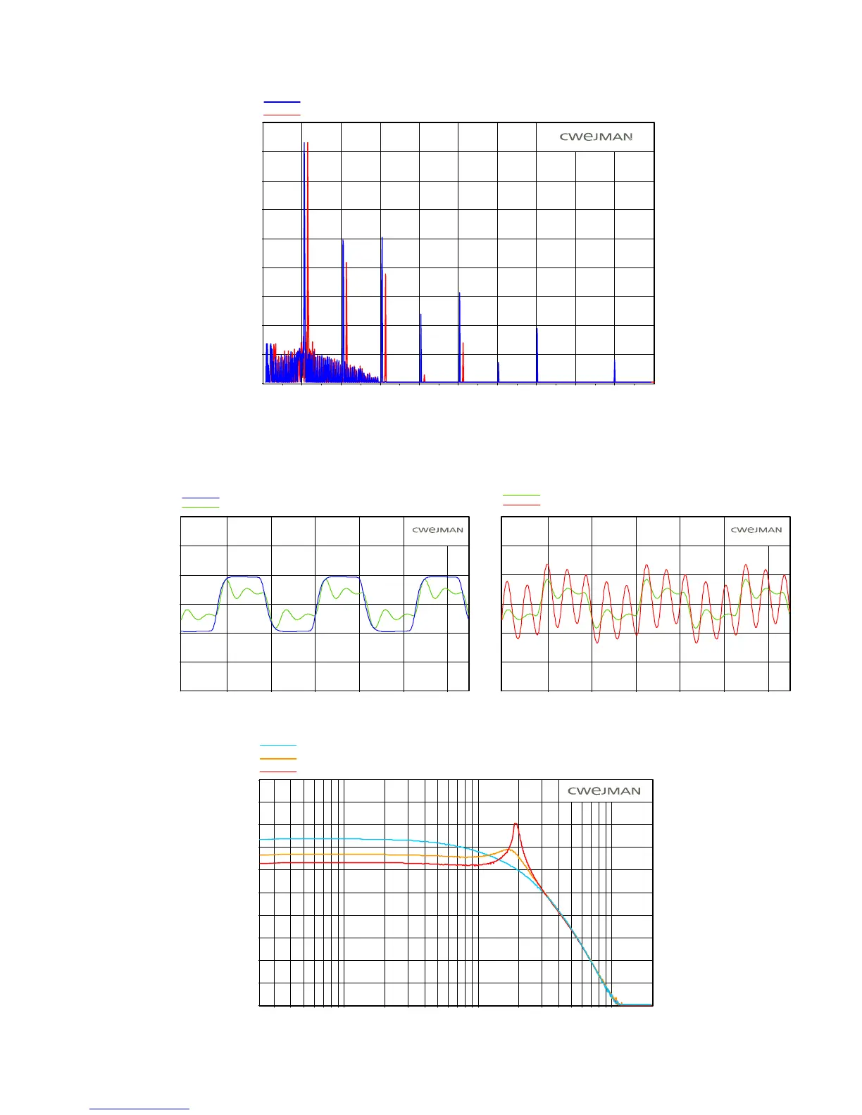
The illustration below shows the suppression of square wave overtones in the LPF.
Q-peak affects the amplitude of the corner frequency from flat to self-oscillation. The illustrations
below show the output signals with variable Q-peak, the frequency response for varying Q-peak and
a swept filter in self-oscillation mode.
dBV rms
0.0
-10.0
-20.0
-30.0
-40.0
-50.0
-60.0
-70.0
-80.0
-90.0
1.0k 3.0k 5.0k 7.0k 9.0k 11.0k 13.0k 15.0k 17.0k 19.0k
Frequency (Hz)
LOW-PASS FILTER, SQR WAVE IN
4-POLE MODE
6-POLE MODE
LOW-PASS FILTER (6 POLE MODE), VARIABLE Q-PEAK
OUTPUT(Volts)
5.0
2.5
0.0
-2.5
-5.0
-7.5
3.00 4.00 5.00 6.00 7.00 8.00
Time (milliseconds)
7.5
Q-PEAK = 0
Q-PEAK = 4
LOW-PASS FILTER (6 POLE MODE), VARIABLE Q-PEAK
OUTPUT (Volts)
5.0
2.5
0.0
-2.5
-5.0
-7.5
3.00 4.00 5.00 6.00 7.00 8.00
Time (milliseconds)
7.5
Q-PEAK = 4
Q-PEAK = 8
dBV rms
-10.0
-20.0
-30.0
-40.0
-50.0
-60.0
-70.0
-80.0
-90.0
-100.0
30 50 70 100 200 300 500 1.0k 2.0k 5.0k 10.0k
Frequency (Hz)
LOW-PASS FILTER, FREQUENCY RESPONSE, VARIABLE Q-PEAK
Q-PEAK = 5
Q-PEAK = 8
Q-PEAK = 0
0.0
41