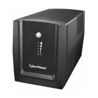
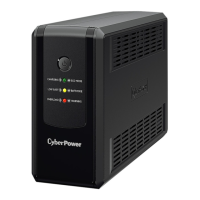
1200E/1500E/2200E
User’s Manual
K01-0000032-01
SAFETY WARNINGS
(SAVE THESE INSTRUCTIONS)
This manual contains important safety instructions. Please read and follow all instructions carefully
during installation and operation of the unit. Read this manual thoroughly before attempting to unpack,
install, or operate your UPS.
This equipment can be operated by any individuals with no previous training.
The socket-outlet shall be installed near the equipment and easily accessible.
During the installation of this equipment it should be assured that the sum of the leakage currents of the
UPS and the connected loads does not exceed 3.5mA.
Attention, hazardous through electric shock. Also with disconnection of this unit from the mains,
hazardous voltage still may be accessible through supply from battery. The battery supply should be
therefore disconnected in the plus and minus pole at the quick connectors of the battery when
maintenance or service work inside the UPS is necessary.
Do not dispose of batteries in a fire, the battery may explode.
Do not open or mutilate the battery or batteries, released electrolyte is harmful to the skin and eyes.
INSTALLING YOUR UPS SYSTEM
UNPACKING
Inspect the UPS upon receipt. The box should contain the following:
UPS Unit¯1; IEC Power Cord¯1;USB Cable¯1;User Manual¯1; Management software Disk¯1
HOW TO DETERMINE THE POWER REQUIREMENTS OF YOUR EQUIPMENT
1. Insure that the equipment plugged into the battery power-supplied outlets does not exceed the UPS
unit’s rated capacity (1200VA/720W for Value 1200E, 1500VA/900W for Value 1500E,
2200VA/1320W for Value 2200E). If rated unit capacities are exceeded, an overload condition may
occur and cause the UPS unit to shut down or the fuse blow.
2. If the power requirements of your equipment are listed in units other than Volt-Amps (VA), convert
Watts (W) or Amps (A) into VA by doing the calculations below. Note: The below equation only
calculates the maximum amount of VA that the equipment can use, not what is typically used by the
equipment at any one time. Users should expect usage requirements to be approximately 60% of
below value.
TO ESTIMATE POWER REQUIREMENTS
1.
Watts (W) x 1.67 = VA or Amps (A) x 230 = VA
2. Add the totals up for all pieces of equipment and multiply this total by 0.6 to calculate actual
requirements. There are many factors that can affect the amount of power that your computer system
will require. The total load that you will be placing on the battery-powered outlets should not exceed
80% of the unit’s capacity.
HARDWARE INSTALLATION GUIDE
Before installation,
please read and understand the following instructions:
1. Placement
The UPS must be installed in a protected environment away from heat- emitting appliances such
as a radiator or heat register. Do not install this product where excessive moisture is present.
2. Ventilation
The location should provide adequate air flow around the UPS with one inch minimum clearance
on all sides for proper ventilation.
3. Charge the Battery
Your new UPS may be used immediately upon receipt. However charge loss may occur during
shipping and storage. So charging the battery for at least 8 hours is recommended to insure that
the battery is fully charged. (To recharge the battery, simply leave the unit plugged into an AC
outlet.)
This UPS can be charged even when UPS is not turn on.
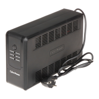
4. Connect to AC
Use German power cord to connect the UPS to a wall
outlet. Please avoid using extension cords and
adapter plugs. (To maintain optimal battery charge,
leave the UPS plugged in at all times.)
5. Connect the Load
Connect the equipment to your UPS outlets. The IEC
power cord coming with the unit are used to connect
your computer and monitor to the UPS. Items such
as copiers, laser printers, vacuums, space heaters,
or other large electrical devices SHOULD NOT be connected to the UPS. Please make sure
that the total loads of your equipments are less than the maximum total power load of your UPS.
6. Connect to Computer:
Install your software and accessories. To use the software, simply use the enclosed serial interface
or USB cable to connect the UPS unit and your computer.
BASIC OPERATION
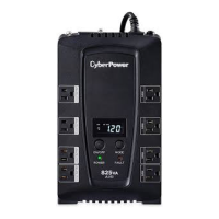
FRONT PANEL DESCRIPTION
1. Power Switch
Press the power switch to turn the UPS ON or OFF.
2. LCD Function Selected Switch
The switch can be used to select the LCD display contents Including input/output voltage
and estimated run time, etc.
REAR PANEL DESCRIPTION
1. AC Inlet
Connect to utility power through the input power cord
2. Input Circuit Breaker
The circuit breaker provides optimal overload protection.
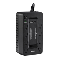
3. AC outlet
The UPS provides 6 outlets for connected equipment to insure temporary uninterrupted operation
during a power failure and against surges and spikes.
4. Serial Port to PC
This port allows connection and communicates
from the DB-9 serial on the computer to the
UPS unit. The UPS communicates its status to
the PowerPanel
®
Personal Edition software. This
interface is also compatible with the UPS service
provided by Windows 98, Windows ME,
Windows NT, Windows 2000, Windows XP,
Windows Server 2003, Windows Vista.
5. USB Port to PC
This port allows connection and communication
from the USB port on the computer to the UPS
unit. The UPS communicates its status to the
PowerPanel
®
Personal Edition software. This
interface is also compatible with the UPS service
provided by Windows 98, Windows ME,
Windows NT, Windows 2000, Windows XP,
Windows Server 2003, Windows Vista.
NOTE: Only one of these two ports
can be used as communication and
control of the UPS unit at one time.
6. Communication Protection Ports RJ11/RJ45
Communication protection ports will protect any standard modem, fax, telephone line, or network
cable.