Assembly and Setup
Page 2–11
Cybex 750C/750R Owner’s Manual
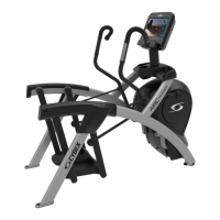
C. Place the console assembly (#2) in the
correct position on the base assembly
(#1) by sliding into position onto the two
mounting screws 5/16-18 x .75” (#11). See
Figure 4.
D. Hand thread the other two screws 5/16-18 x
.75” (#11). See Figure 3.
E. Securely fasten the four screws 5/16-18 x
.75” (#11) with a 1/2” socket wrench.
NOTE: Ensure cable connectors click together and
are securely fastened.
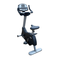
F. Locate the upper display cable
connector and plug it into the
lower display cable
connector. See Figure 5.
G. Locate the upper heart rate
connector and plug it into the
lower heart rate connector. See
Figure 5.
NOTE: Do not pinch or damage the cables
during assembly.
H. Tuck each of the cable connectors
into the top hole in the frame. See
Figure 5.
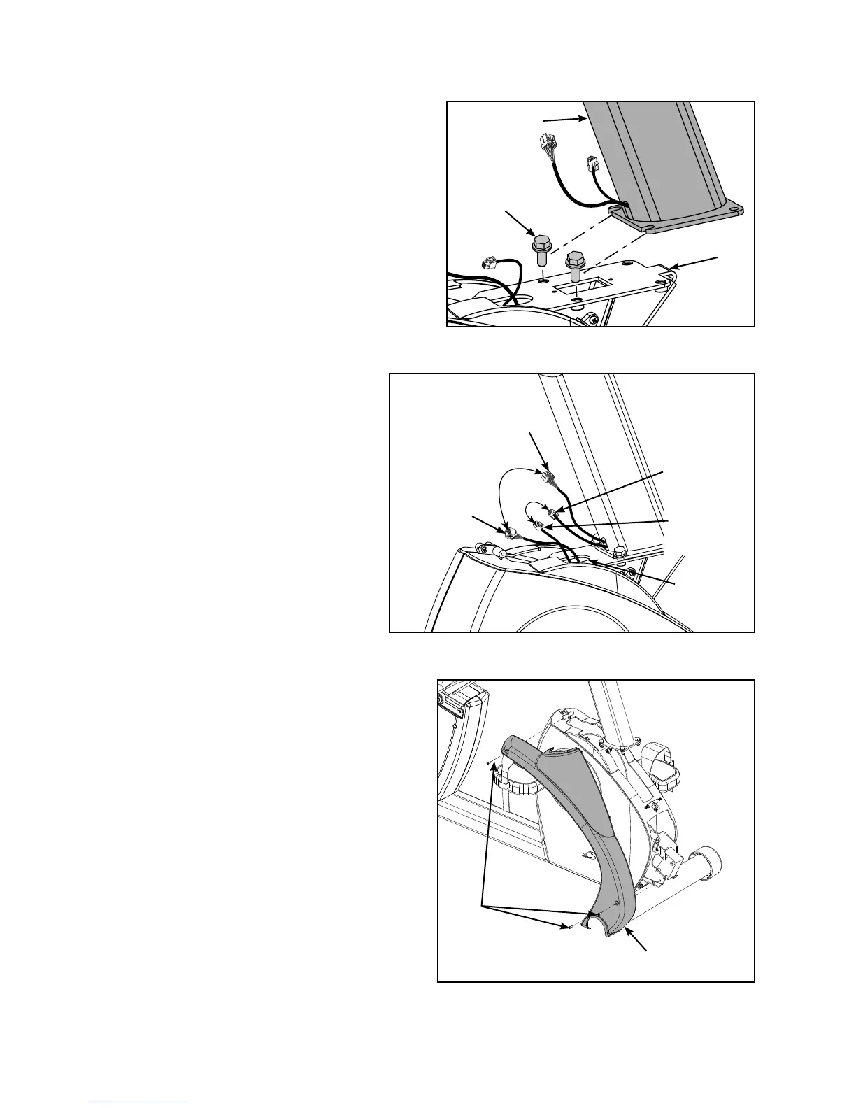
5. Install the front covers.
A. Locate and place the front right
cover (#4) on the front of the unit as shown
in Figure 6.
B. Using a Phillips screwdriver, secure with
three screws 8-16 x .50” (#13). See
Figure 6.
NOTE: In addition to two mounting screws per front
cover, there are fi ve plastic connectors that
secure the front covers together. Ensure
that all four plastic connectors are inserted
properly in each front cover. See Figure 7.
Figure 5
Upper
Display
Connector
Upper
Heart Rate
Connector
Top Hole
In Frame
Lower
Display
Connector
Lower
Heart Rate
Connector
Figure 6
#13
#4
Figure 4
#11
#2
#1
 Loading...