2. Remove the access cover.
A. Using a Phillips head screwdriver, loosen the four screws securing the access cover. See
Figure 2.
B. Remove the access cover.
3. Remove the console assembly.
A. Using an Allen wrench, remove the four screws and four lock washers securing the console
assembly in place.
B. Carefully lift console assembly and disconnect the upper display cable from the lower display
cable. See Figure 29.
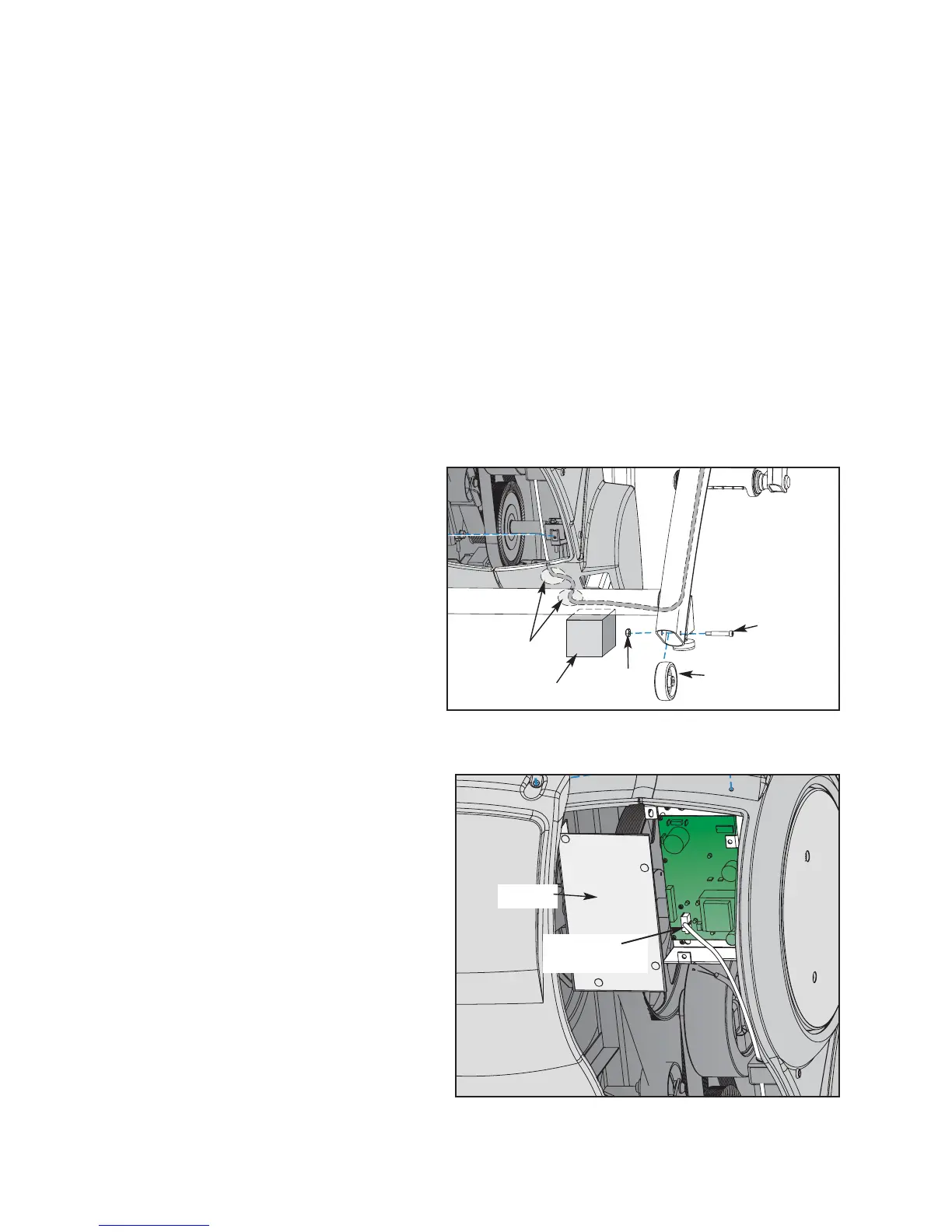
4. Remove the left wheel.
A. Place a wooden block under the unit to take the weight off the left wheel.
B. Using a 9/16” wrench and a 3/16”
Allen wrench, remove the bolt and nut
securing the left wheel in place. See
Figure 30.
5. Detach the lower display cable.
! WARNING: Do not touch components on
the lower board. A charge can
remain after unplugging the
power cord and turning off the
unit.
A. Pull out on the lower board shield.
NOTE: It will snap out.
B. Disconnect the display cable from the
lower board. See Figure 31.
C. Remove the lower display cable from
the wire holder bracket. See Figure 31.
6. Attach the new lower display cable.
A. Using wire cutters, cut both sets of the
old contact heart rate cables from
the old lower display cable (these are
the small pairs of brown and black
cables). See Figure 29.
NOTE: The heart rate cables have a left and a
right side, they must be wired correctly.
Cybex Arc Trainer 610A Service Manual
Service
Page 4-38
Figure 30
Figure 31
Shield
P1 on
Lower Board
Access
Holes
Block
Wheel
Bolt
Nut

 Loading...