CYRUS CD6s TECHNICAL DESCRIPTION
© Cyrus Audio Ltd Nov 2006 7 Cyrus CD6s Service Manual Issue 2
The DAC master clock is generated by the PLL circuit IC204 (74HC4046) and divided by shift
register IC205 (74HC161). O/P Pin11 (÷16) XCLK/8 = 2.1168MHz.
O/P Pin14 (÷2) XCLK = 19.99344MHz.
The DAC regulated power supplies are derived from the low voltage secondary windings: +5V
(VR604) and +3.3V (VR301).
Digital Optical output
The reformatted data from IC202 (74HC574) is converted to SPDIF format by the digital audio
output encoder IC101 (AK4103) then fed to the optical output (TOTX101).
Power supplies
The internal regulated power supplies for the Cyrus CD6s are derived from the high and low
voltage secondary windings from a single toroidal transformer.
The low voltage windings supply regulated +5V supplies to digital circuitry including the PLL,
DtoA converter, microcontroller and CD mechanism.
The high voltage windings supply regulated ±15V supplies to the analogue audio stages and a
+9V supply to the servo control motors for CD mechanism.
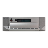
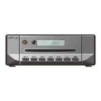
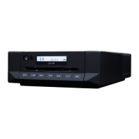
Front panel display
The front panel display is a backlit LCD module mounted in a moulding behind the front panel.
The LCD module is driven by signals from microcontroller IC502 pins 52 and 53 (LCD_DATA
and LCD_SCLK). IC502 also reads back an analogue voltage encoded from keys pressed on the
front panel (via KEYS_IN1 pin 64), and remote control information from the eye via line
REMOTE_IN pin 43.