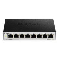
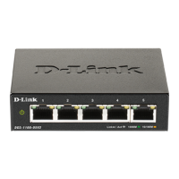
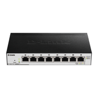
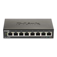
2 Hardware Installation D-Link Smart Managed Switch User Manual
9
9
Step 2. Hook the mounting keyholes on the back of the Switch onto the screws to secure the device to
the wall.
Figure 2.2 – Wall mount installation
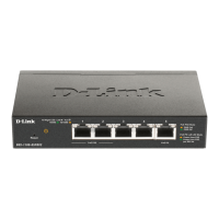
Metal screw (M7 type; Length 16 mm, Number of screws *2) for DGS-1100-05V2/05PDV2/08V2/08PV2
Vis métallique (type M7 ; longueur 16 mm, nombre de vis *2) pour DGS-1100-05V2/05PDV2/08V2/08PV2
 Loading...
