This document provides general instructions for the storage, installation, and use of the E2D series electric panels, including models E2D 2.6 M, E2D 6 M, E2D 6 M HS, E2D 2 T, E2D 3 T, E2D 5 T, E2D 5 T (230v), E2D 8 T, E2D 15 T, E2D 16 T, E2D 15 T SD, E2D 30 T SD, E2D 40 T SD, E2D 50 T SD, and E2D 60 T SD. These devices are designed to control and protect submersible electropumps and circulating pumps installed in pairs.
Function Description
The control panel is self-protected and protects the electropumps against overloads, short circuits, and overtemperatures, with manual reset. It features automatic inversion of the starting order of the two electropumps at each start, simultaneous operation, and the ability to run one pump if the other malfunctions.
The panel is supplied standard with terminals for connecting motors P1 and P2, and control floats GP1 and GP2. It also includes terminals for an alarm float and potential-free terminals for remote acoustic or visual alarms. Each electropump has a selector for manual or automatic operation.
For the E2D 6 M HS model, an automatic device increases the static torque time during startup, factory-set to 2 seconds (do not set over 4 seconds). The internal transformer is protected against overloads or short circuits with automatic reset, manually cutting out the supply voltage for 3 minutes. Some models have the transformer protected by a fuse.
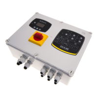
The electronic module SZ2 manages the panel's operation, providing automatic inversion of the starting order of the two electropumps at each start. A green LED (LL1) on the SZ2 module indicates the status of the controls.
- System without dry alarm float (N terminals 21-22):
- LL1 is solid green when GP1 + GP2 = OFF (both pumps stopped).
- LL1 flashes once per second when GP1 = ON and GP2 = OFF (one pump running).
- LL1 flashes twice per second when GP1 + GP2 = ON (both pumps running).
- System with dry alarm float (N terminals 21-22):
- LL1 is solid green when the dry alarm float = ON and GP1 + GP2 = OFF (both pumps stopped).
- LL1 flashes when the dry alarm float = OFF and GP1 + GP2 = OFF or ON (both pumps stopped).
- LL1 flashes once per second when the dry alarm float = ON, GP1 = ON and GP2 = OFF (one pump running).
- LL1 flashes twice per second when the dry alarm float = ON and GP1 + GP2 = ON (both pumps running).
- System with maximum level float (R terminals 35-36): Operation is the same as with the dry alarm float.
When the SZ2 module is active, the starting order of the two pumps is inverted at each start, so P1 and P2 identifications are indicative.
If the SZ2 module is excluded (selector SA1 in position), the start and stop commands for the electropumps are given directly by the two floats or thermostats: GP1 controls P1, and GP2 controls P2. The LL1 LED indications remain as described above.
If the SZ2 module is disconnected from the electric panel (connecting XC1 to XC2, with SA1 in position), the start and stop commands are also given directly by the two floats GP1 and GP2. However, this limits the system's operation: float cable length must not exceed 10m, the minimum level float function is excluded, repeated starts are not controlled, and thermal protections (K-K terminals) are excluded. It is advisable to replace the SZ2 module promptly in such cases.
Important Technical Specifications
- Rated Input Voltage:
- E2D 2.6 M, E2D 6 M, E2D 6 M HS: 220 - 240 V +/- 10% (1 phase)
- E2D 2 T to E2D 60 T SD: 400 V +/- 10% (3 phases)
- Frequency: 50-60 Hz
- Number of Pumps: 2
- Max. Rated Output Power (kW) and Current (A):
- E2D 2.6 M: 1.85kW + 1.85kW, 10 + 10 A
- E2D 6 M, E2D 6 M HS: 2.95kW + 2.95kW, 16 + 16 A
- E2D 2 T: 1.38kW + 1.38kW, 2.5 + 2.5 A
- E2D 3 T: 2.2kW + 2.2kW, 4 + 4 A
- E2D 5 T: 4.36kW + 4.36kW, 6.3 + 6.3 A
- E2D 5 T (230v): 3kW + 3kW, 10 + 10 A
- E2D 8 T: 5.5kW + 5.5kW, 10 + 10 A
- E2D 15 T: 7.7kW + 7.7kW, 14 + 14 A
- E2D 16 T: 9.9kW + 9.9kW, 18 + 18 A
- E2D 15 T SD: 5.5kW + 5.5kW, 16 + 16 A
- E2D 30 T SD: 13.8kW + 13.8kW, 25 + 25 A
- E2D 40 T SD: 17.7kW + 17.7kW, 32 + 32 A
- E2D 50 T SD: 18.5kW + 18.5kW, 45 + 45 A
- E2D 60 T SD: 22kW + 22kW, 63 + 63 A
- Starting Capacitor:
- E2D 2.6 M: --
- E2D 6 M, E2D 6 M HS: 40μF + 40μF
- Capacitor for Strong Static Torque (E2D 6 M HS only): 200-250μF + 200-250μF
- Environment Temperature: -10°C to +40°C
- Storage Temperature: -25°C to +55°C
- Relative Humidity (without condensation): 50% at 40°C MAX (90% at 20°C)
- Max. Altitude: 3000 m (a.s.l.)
- Degree of Protection: IP55
- Construction: According to EN 60204-1 and EN 60439-1
Usage Features
- Installation: Panels must be installed on dry, vibration-free surfaces. While IP55 rated, avoid atmospheres with oxidizing or corrosive gases. If installed outdoors, protect from direct sunlight. Maintain internal temperature within specified limits to prevent component aging. Ensure watertight cable clamps. Use provided gripping rings to secure cables. Mount panels using the four standard brackets, utilizing only the designated slots to maintain IP55 rating.
- Starting the Set: Ensure external controls (floats/thermostats) are OFF. Turn SB1 (P1) or SB2 (P2) to MAN for manual pump operation. For automatic operation, floats B and C control P1 and P2 respectively, with float B also providing minimum level stop for both pumps (two-float system). For three-float systems, float A provides minimum level stop. Dry-run (N) or maximum pressure (R) floats block pump operation if activated.
- Protection System: Dry-run protection is activated by connecting the float to N terminals (21-22). Overflow protection is activated by connecting the float to R terminals (35-36). Simulate float intervention to verify correct operation; the panel should stop pumps, and HL2 should light up.
- Alarm System: Check alarm float (P terminals 25-26) and remote alarm (Q terminals 31-32) operation. The remote alarm contact is potential-free. The alarm system power circuit must be PELV (CEI EN 60204-1) compliant; otherwise, ensure the float's earth lead is connected to the earth terminal.
- Circulating Pumps/Booster Sets: To configure the panel for in-line circulating pumps or domestic booster sets, remove the jumper O connected to terminals 23-24.
Maintenance Features
- Troubleshooting: The manual provides a detailed troubleshooting guide for various issues, including:
- Motor not fed: Check magnetothermal switches (QM1/QM2), differential switch, power supply (L1-N), internal transformer protection, and fuses (FU1/FU3/FU4). Verify cable insulation and connections.
- QM1/QM2 intervention: Check for blocked pump impellers (P1/P2) and correct timer settings (KT1/KT2).
- Thermal protection trip: Check ambient temperature, blocked impellers, and rotor shaft bearings. Reduce fluid temperature or replace bearings if worn.
- Pump not responding to external commands: Check float connections, float functionality, remote control switch (KM1/KM2) status, and SZ2 module functionality.
- No automatic pump order inversion: Check KA1 relay coil and SZ2 module.
- Intermittent KM1/KM2 power: Check motor cable connections.
- General Maintenance: Before any maintenance, disconnect power. Ensure all terminals are fully tightened. Periodically check cable conditions.
- E2D 6 M HS Specific: Dimension the hydraulic system to limit starts to 20 per hour (1 start every 3 minutes).
- Thermal Protection (KK): For pumps with KK thermal protection, remove the jumper from the KK terminals on the control panel and connect the pump's protection cables to these terminals.