ENGLISH
The apparatus must be correctly and safely earthed as required by the
regulations in force.
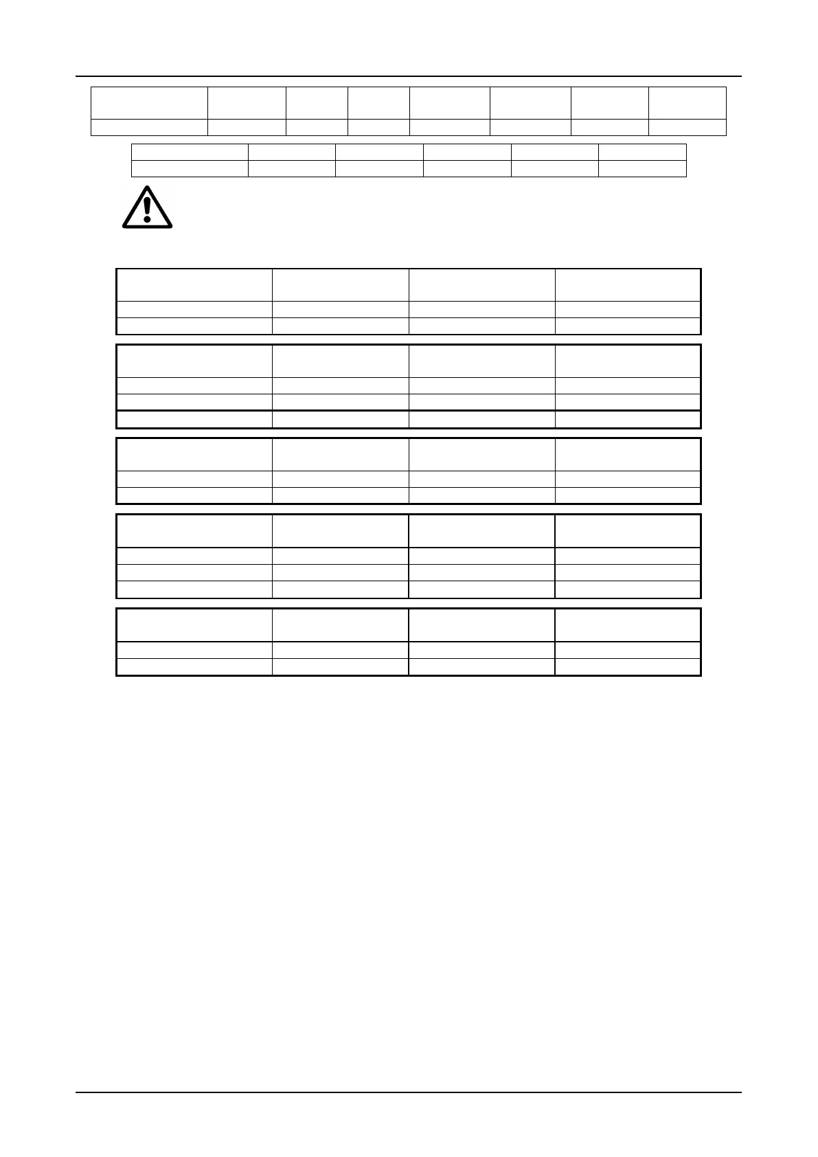
Depending on the type of installation, limit the maximum length of the power cable as follows:
Max. line length
Cable Ø 1.5 mm
Max. line length
Cable Ø 2.5 mm
Max. line length
Cable Ø 4 mm
Max. line length
Cable Ø 2.5 mm
Max. line length
Cable Ø 4 mm
Max. line length
Cable Ø 6 mm
Max. line length
Cable Ø 6 mm
Max. line length
Cable Ø 10 mm
Max. line length
Cable Ø 16 mm
Max. line length
Cable Ø 16mm
Max. line length
Cable Ø 25 mm
Max. line length
Cable Ø 35 mm
Max. line length
Cable Ø 16mm
Max. line length
Cable Ø 25 mm
Max. line length
Cable Ø 35 mm
Instrumental checks to be carried out by the installer:
a) continuity of the protection leads and of the main and supplementary equipotential circuits;
b) insulation resistance of the electric system;
c) test efficiency of the differential protection;
d) test the applied voltage;
e) test operation as indicated in points 9.5, 9.6, 9.7.
Supplying power to the control panel
After having correctly performed the steps described above, turn the selectors ref. SA1 and SA2 to position 0 and close
the panel door. Supply power to the control unit, switching on the main switch on the distribution panel. Turn on the
isolating switch ref. QS1 on the panel door. The electropumps are not fed.
.
1. Ensure that the external controls are turned OFF (control excluded).
2. Turn the selector ref. SB1 to MAN position. The electropump P1 is fed as long as the manual impulse lasts. Repeat
the operation with selector ref. SB2. The electropump P2 is fed as long as the manual impulse lasts.
− For systems with two floats; following the indications in fig. page 117 the start command for pump P1 is given by
the float B, connected to the terminals 3-4, and the start command for pump P2 is given by the float C, connected to
the terminals 5-6. The stop command for both pumps is given by the float B in minimum position.
− For systems with three floats; following the indications in fig. page 117 the start command for pump P1 is given
by the float B, connected to the terminals 3-4, and the start command for pump P2 is given by the float C,
connected to the terminals 5-6. The stop command is given by the float A, connected to the terminals 1-2, which
acts as a minimum level float for both pumps.
 Loading...