6
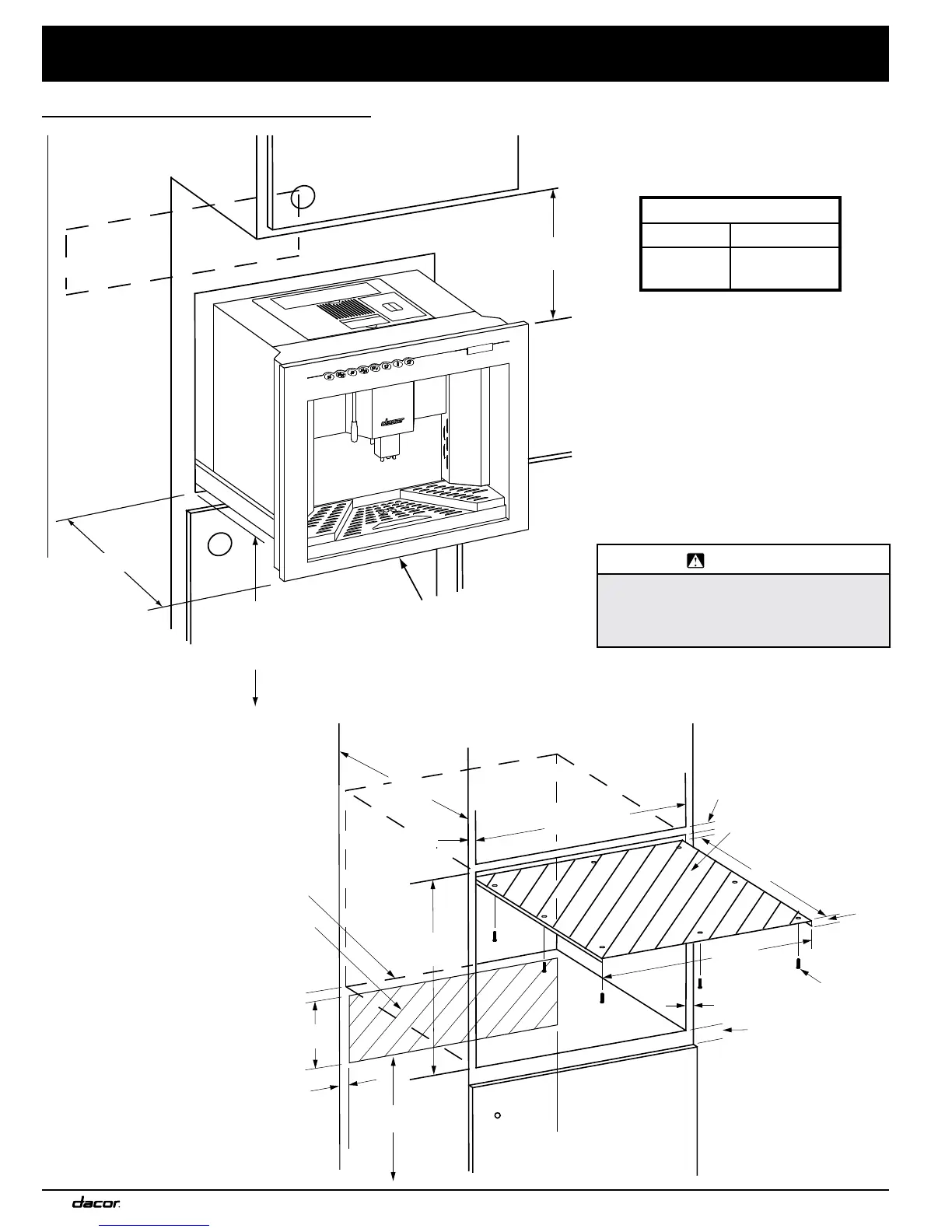
InstallatIon specIfIcatIons
17 7/8”
(454mm)
1” (26mm)
Screw 8 places
(provided)
3/4” (19mm)
Level Support Platform
24”
(610mm)
Steam Barrier
(provided)
Optimal Water
and Electrical
Supply Location
20 3/4”
(527mm)
1/8”
(3mm)
22 3/16”
(564mm)
1” Min.
(26mm)
1” Min. (26mm)
3/4” (19mm)
Min. Side Walls
22 1/8” - 22 3/8”
(562mm - 568mm)
8””
(203mm)
6” (152mm) min.
to room floor
3/4” (19mm)
Min. Side Walls
nomInal cutout dImensIons
Coffee maker pulled
out from cabinet
Overhanging
cabinet
Veritical distance
to overhanging cabinet
22” (559mm)
Min. distance to
floor of room: 1” (25.4mm)
Max. recommended
distance to floor of room:
36” (914mm)
Ventilation opening in
back of cabinet
4” X 12” Min.
(100mm X 300mm)
Vertical Distance
CM24T-1 14” Minimum
CM24P-1 6” Minimum
14” Minimum
During normal operation, the user must
have access to the top of the unit. The
user needs to be able to pour coffee into
the coffee bins on top and, on model
CM24T,-1 be able to remove the water
tank for filling and cleaning. Install the
coffee maker low enough so that the user
can reach the top of the unit easily when
it is slid out of the cabinet.
All tolerances are + 1/16”, - 0”
(+1.6mm, -0) unless otherwise stated.
WARNING
Electric Shock Hazard: Due to steam and
spillage during normal use, DO NOT install
this appliance above or below any other
appliance.
 Loading...