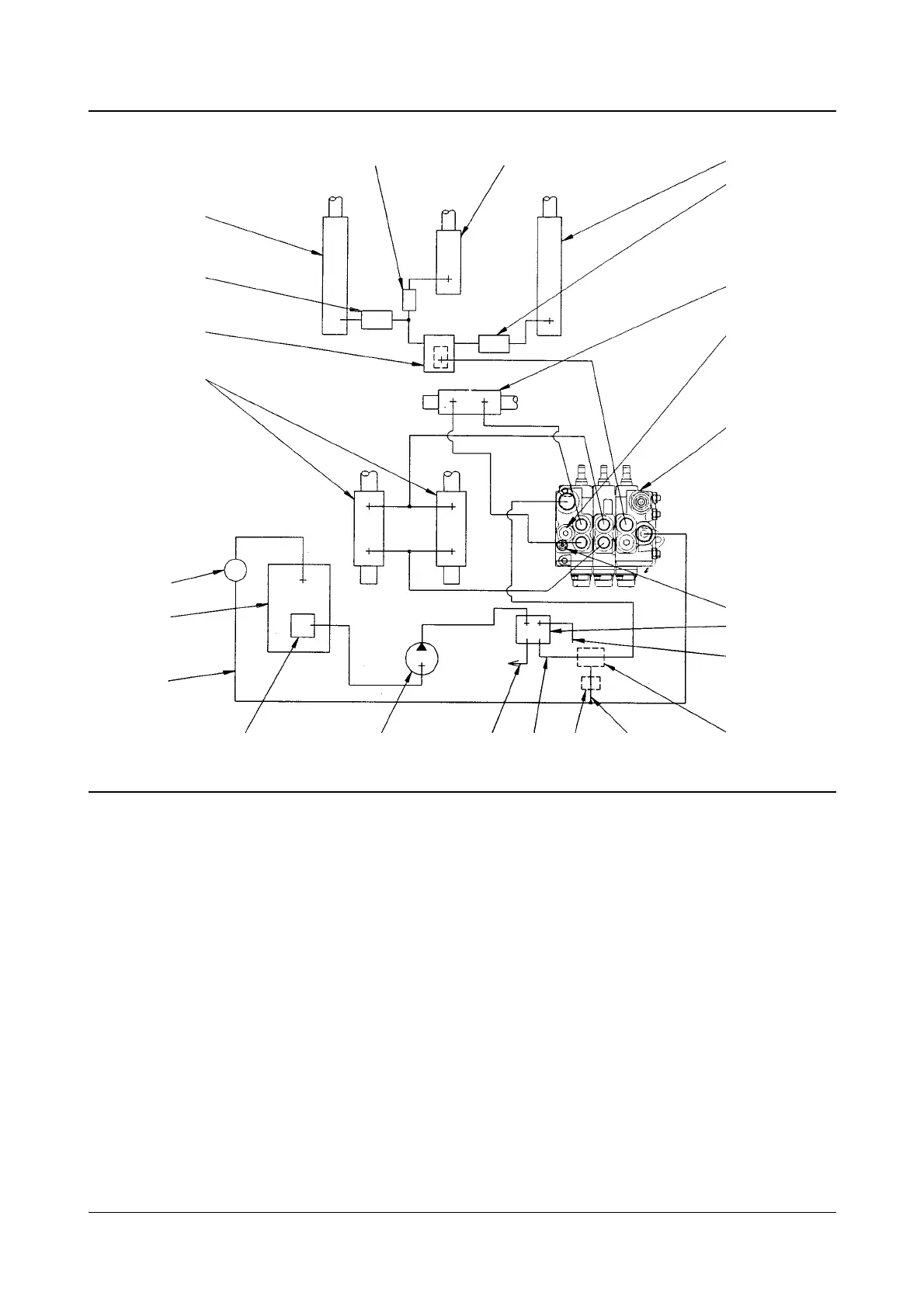
The maximum speed at which the lift cylinder(s) are
lowered is controlled by lowering flow control valve (4).
Excess flow protectors (2) and (21) will act as flow
control valve if an oil line between them and flow
control valve (4) is broken when the mast is raised or
lowered. This prevents a sudden fall of the mast or
carriage if an oil line is broken.
The tilt forward, tilt back and sideshift speeds are
controlled by flow control valves in hydraulic control
valve (5). There is an anti-cavitation valve inside the
tilt spool to prevent cavitation (development of air
pockets) in tilt cylinders (6).
REFERENCE : For the Hydraulic Systems Schematics.
13 of 29New Hydraulic Systems Systems Operation
Basic Hydraulic Schematic With Standard Lift
(1) Lift cylinders. (2) Excess flow protectors. (3) Sideshift cylinder(s)(if equipped). (4) Lowering folw control valve. (5) Hydraulic
control valve. (6) Tilt cylinders. (7) Relief valve(lift). (8) Relief valve(tilt and sideshift). (9) Hydraulic oil filter. (10) Hydraulic oil
tank. (11) Priority valve. (12) Oil line(trucks with power brakes only). (13) Oil line. (14) Hydraulic strainer. (15) Hydraulic pump.
(16) Oil line to steering gear. (17) Oil line. (18) Remote relief valve. (19) Oil line(trucks with anti-stall valve only). (20) Anti-stall
valve. (21) Excess flow protector. (22) Lift cylinder(primary).
6
4
2
1
9
10
13
14
15
16
17 18
19
20
12
11
5
7
3
2
1
2221
8
IDCS005B