Specifications
Hydraulic Control valve
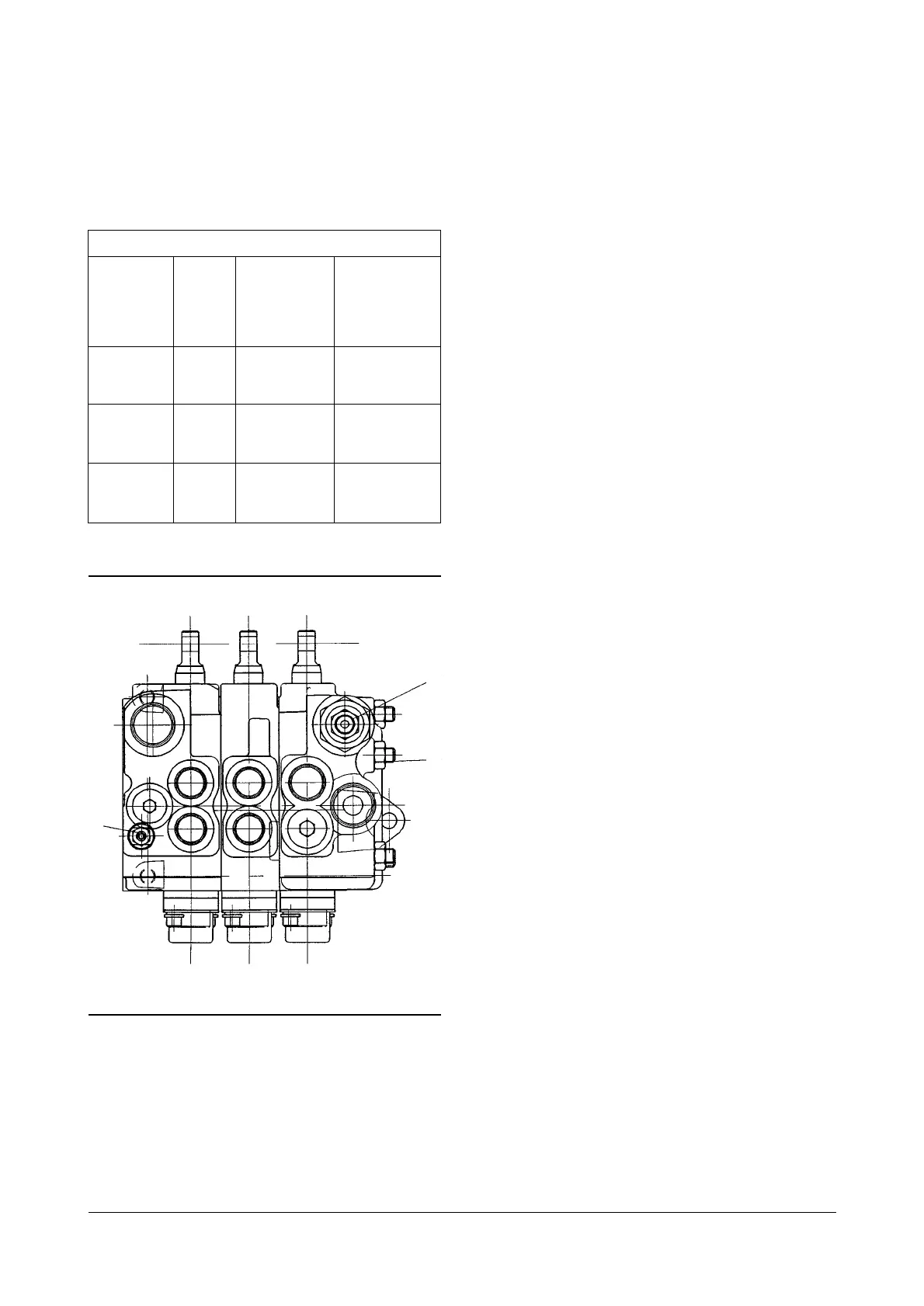
(1) Torque for bolts that hold control valve sections
together
................
40.5
± 2 N
•
m (360 ± 18 lb
•
in)
(2) Adjust TILT and sideshift relief valve pressure as
shown above. See Relief Valve Pressure Check
in Testing And Adjusting.
(3) Torque for nipple assembly
........
36.5
± 0.5 N
•
m
(320
± 4 lb
•
in)
See Folw Control Valve Adjstment in Testing And
Adjusting.
(4) Torque for screws
............................
12 ± 1.5 N
•
m
(105
± 13 lb
•
in)
5 of 29New Hydraulic Systems Specifications
CONTROL VALVE
TILT, Auxiliary
Relief Valve
Pressure
± 350 kPa
(
± 50 psi)
15,500 (2250)
15,500 (2250)
15,500 (2250)
Main Relief
Valve
Pressure
± 500 kPa
(
± 75 psi)
18,100 (2625)
19,500 (2825)
21,550 (3125)
Mast
Std
FFL
FFTL
Std
FFL
FFTL
Std
FFL
FFTL
Model
D(G)20(S)
GC20(S)
D(G)25(S)
GC25(S)
D(G)30S
GC30S
2
1
3
IDCS001B