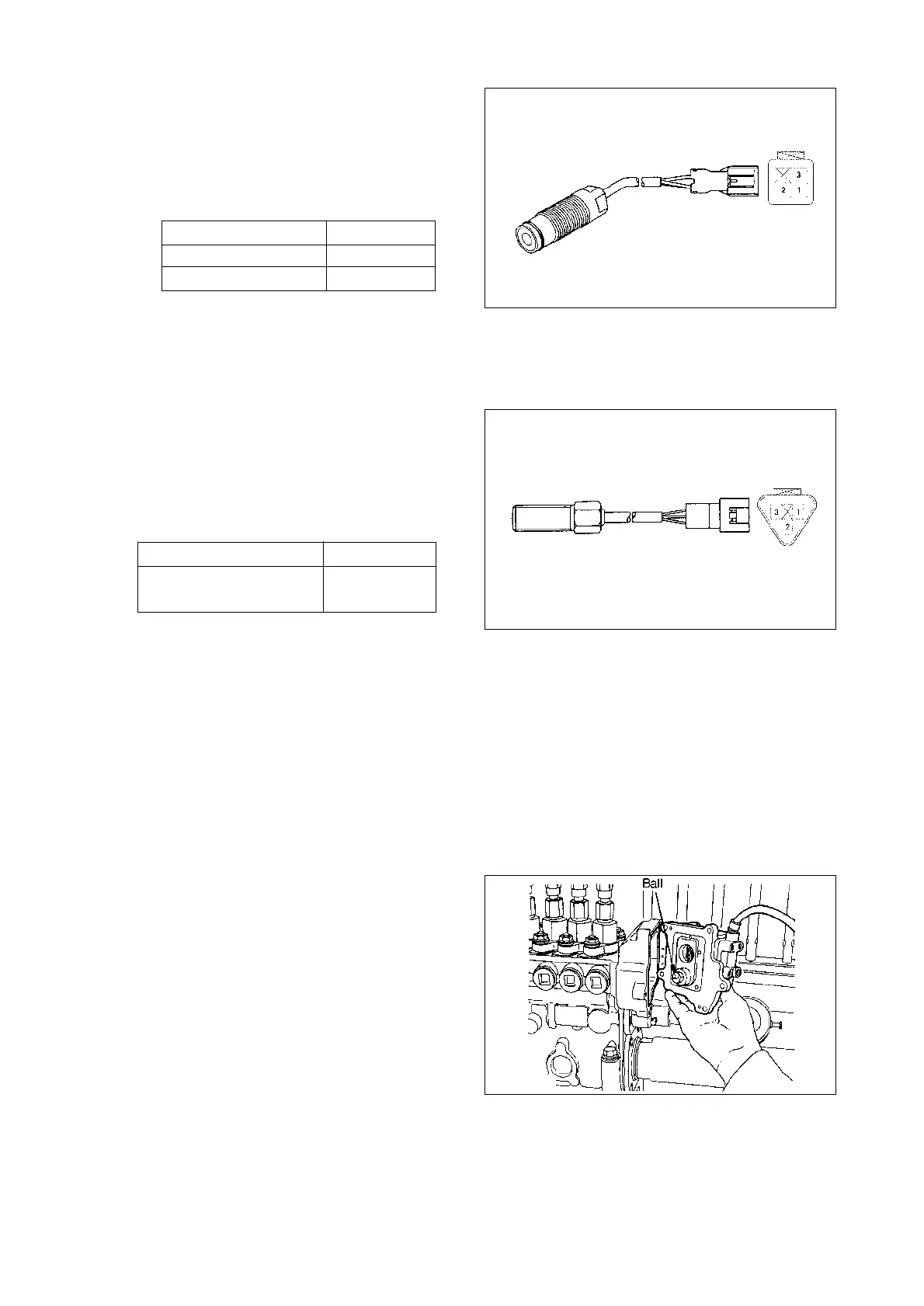
(3) Check the resistances between each
of the rack sensor terminals shown in
the figure using a circuit tester. Their
resistances at 25˚C are shown in the
table below.
Also, check that the resistance
between the terminals and the hous-
ing is
∞.
Wire color Resistance(
Ω)
Red(OSC)~White(MID) 92.5~101.5
Black(GND)~White(MID) 92.5~101.5
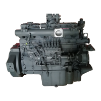
(4) Check the resistances between the
speed sensor terminals (if installed)
shown in the figure using a circuit tester.
Their resistance is snown in the table
below
Note : The above apply to speed sen-
sors with the following part
numbers.
479748-6201
479748-6600
479748-6800
Also, check that the resistance between
the terminals and the housing is
∞.
Wire color
Resistance(k
Ω)
Yellow(SIGNAL)~
2.1~2.5
Black(GND)
3) Pre-stroke actuator installation
(1) Insert the ball on the end of the actu-
ator’s shaft into the top of the U-
shaped link’s opening.
Temporarily tighten the pre-stroke
actuator’s five bolts.
Specified torque :
1.0~4.9 N•m(0.1~0.5 kgf•m)
Note : When installing the actua-
tor, turn it as far as possible
clockwise (viewed from the
drive side) to facilitate later
adjustment.
- 122 -
EA2M4005
EA2M4006
EA2M4007