INSTALLATION (CONTINUED)
8
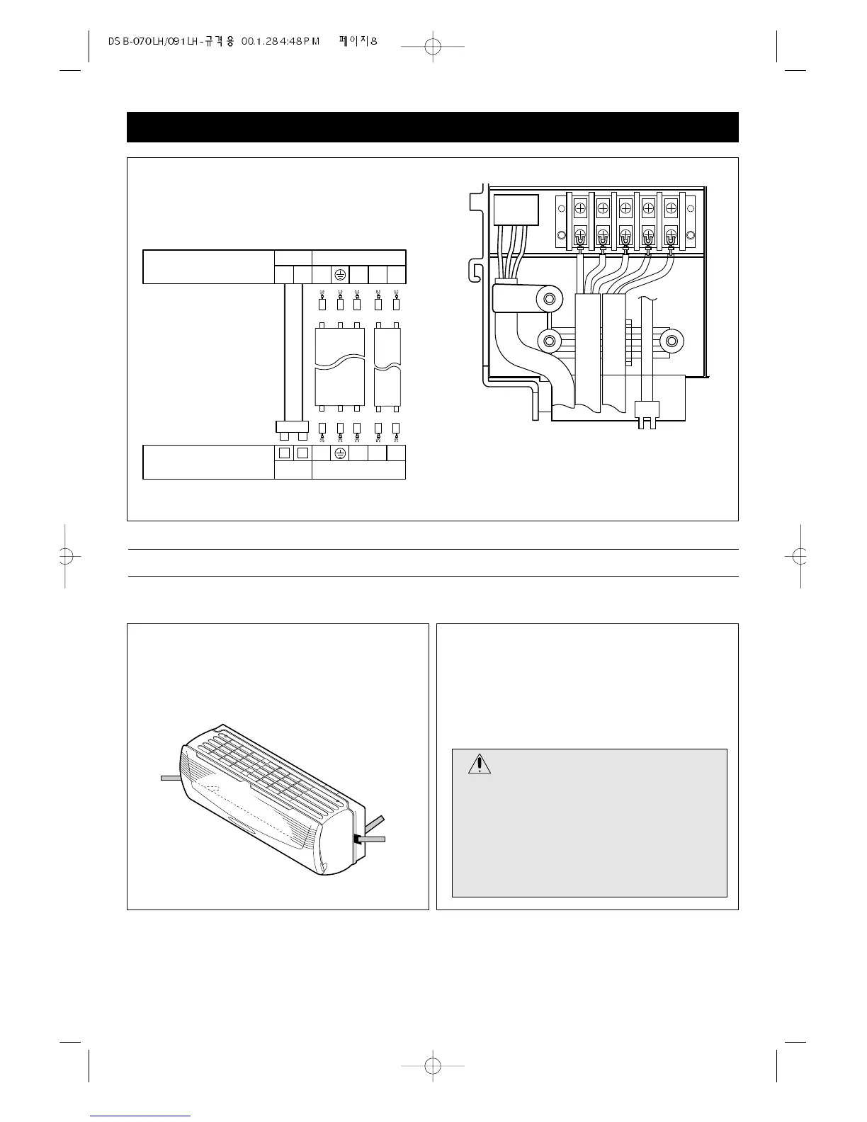
4. Connect the wires to the housing and terminals on
the control board individually according to the out-
door unit connection.
The used connection cable connected to indoor and out-
door unit must be ;
1) H07RN-F 3G1.5mm
2
(NOT INCLUDED)
2) H07RN-F 2G1.5mm
2
(NOT INCLUDED)
3) UL2464 AWG22 2G0.75mm
2
(INCLUDED IN SET)
Housing & Terminals on the
outdoor unit
Housing B
GRAY
color of wires
color of wires
BLACK
GRAYBLACK
Housing A
Black
Brown
Yellow/
Green
Blue
Black
Brown
Yellow/
Green
Blue Blue
Blue
Y 1L 2
Terminals
Housing & Terminals on the
indoor unit
Main PCB Terminals
Y 1L 2
<INDOOR UNIT (Control Box)>
Hausing
A
1) 2) 3)
2. Make sure the drain hose and copper tubing are
wrapped with the rubber insulation. Using the tape,
wrap the indoor/outdoor wire, copper tubing and
drain hose together.
MOUNTING THE INDOOR UNIT
The Indoor unit must be mounted before connecting the indoor/outdoor wire, drain hose and copper tubing. To mount,
follow the procedures below:
1. The tubing can be extended in 4 directions as shown
below. No cutting is necessary for left/rear and
right/rear tubing connections. If using left or right tub-
ing connections, remove the plastic area with a hack-
saw so pipes can go through.
CAUTION:
• Make sure the Indoor unit’s AC cord is not con-
nected to AC power when performing these pro-
cedures.
• Be sure to comply with local codes on running a
wire from the indoor to the outdoor unit.
• DO NOT LET THE INDOOR/OUTDOOR WIRE
COME IN DIRECT CONTACT WITH THE TUB-
ING OR HOSE!



 To Next Page