EasyManua.ls Logo

Daewoo DSB-122LH User Manual

Daewoo DSB-122LH
139 pages
To Next Page IconTo Next Page
Page #1 background imageLoading...
Page #1 background image
Service Manual
Split System Air
Conditioner
Model: DSB-070LH/DSB-071LH
DSB-091LH/DSB-092LH
DSB-121LH/DSB-122LH
DSB-123LH
DSB-182LH/LH-R
DSA-183LH-R
DSB-240LH-R
DSA-240LH-R
DAEWOO ELECTRONICS CO., LTD.
by Nemko
Question and Answer IconNeed help?

Do you have a question about the Daewoo DSB-122LH and is the answer not in the manual?

Daewoo DSB-122LH Specifications

General IconGeneral
BrandDaewoo
ModelDSB-122LH
CategoryAir Conditioner
LanguageEnglish

Summary

1. SPECIFICATIONS

Model Specifications Overview

Detailed specifications for various Daewoo air conditioner models.

2. OUTLINE AND DIMENSIONS

Indoor Unit Dimensions

Diagrams showing the physical dimensions of indoor units.

Outdoor Unit Dimensions

Diagrams showing the physical dimensions of outdoor units.

3. OPERATION

Indoor Unit Parts and Functions

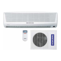
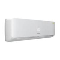
Identifies and describes parts of the indoor unit.

Outdoor Unit Components

Identifies key components of the outdoor unit.

2 REMOTE CONTROLLER

Remote Controller Buttons and Functions

Explains the function of each button on the remote controller.

Remote Controller Display Indicators

Describes the symbols and indicators on the remote control display.

4. WIRING DIAGRAM

Indoor Unit Wiring Diagrams

Electrical wiring diagrams for indoor units.

Outdoor Unit Wiring Diagrams

Electrical wiring diagrams for outdoor units.

5. REFRIGERANT CYCLE

Refrigerant Cycle Diagram and Charge Quantities

Illustrates the refrigerant cycle and lists refrigerant charge amounts.

6. CONTROL BLOCK DIAGRAM

Control Block Diagram for Specific Models

Shows the control system architecture for various models.

7. TROUBLE SHOOTING

General Troubleshooting Flowchart

Guides for diagnosing and resolving common operational issues.

Self-Diagnostic Function and Error Codes

Explains error codes and the self-diagnostic function.

Specific Unit Operation Faults

Addresses common problems like non-running units or fans.

8. KEY COMPONENTS OF ELECTRONIC CIRCUIT

MICOM (U1) Pinout and Functions

Details the pinout and functions of the MICOM IC.

Other Key Electronic Components

Identifies voltage regulators, reset ICs, and other components.

9. DISASSEMBLY INSTRUCTIONS

Indoor Unit Disassembly Procedures

Step-by-step guide for disassembling the indoor unit.

Outdoor Unit Disassembly Procedures

Step-by-step guide for disassembling the outdoor unit.

3 EXPLODED DIAGRAM (Indoor Unit)

Indoor Unit Exploded Views by Model

Visual breakdown of indoor unit parts for different models.

4 EXPLODED DIAGRAM (Outdoor Unit)

Outdoor Unit Exploded Views by Model

Visual breakdown of outdoor unit parts for different models.

5 CONTROL BOX ASSEMBLY

Control Box Component Layouts by Model

Diagrams showing control box components for various models.

Related product manuals