43 44
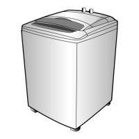
OSCILLATION UNIT
1. CIRCUIT DIAGRAM
2. EXPLANATION OF CIRCUIT
• As the OSCILLATION UNIT is a basic part of the MICOM DRIVE. If the oscillation doesn’t generate, we
able to consider that the MICOM is destroyed.
• The waveform between the part of 1 The waveform between the part of 2
and the GND and the GND
• Specification of oscillator
• It is general use for the MICOM maker’s recommendatory value of condenser which is fit for MICOM’s
characteristics.
• The R82(10MΩ, 1/6W) is in use to get rid of the initial abnormal oscillatory phenomenon of the 32.768
KHz crystal oscillator.
Murata 3 Terminal
Ceramic Resonator
(CST 12.00MTW)
Kyocera 32.768 KHz
Crystal Oscillator
(KF-38G-13P0200)
CONDENSER
TYPE OF OSCILLATOR MAKER NAME OF OSCILLATOR
C1 C2
12 MHZ
MURATA CST 12.00 MTW 33 PF 33PF
CERAMIC RESONATOR
32.768KHZ
KYOCERA KF-38G-13P0200 18PF 18PF
CRYSTAL OSCILLATOR
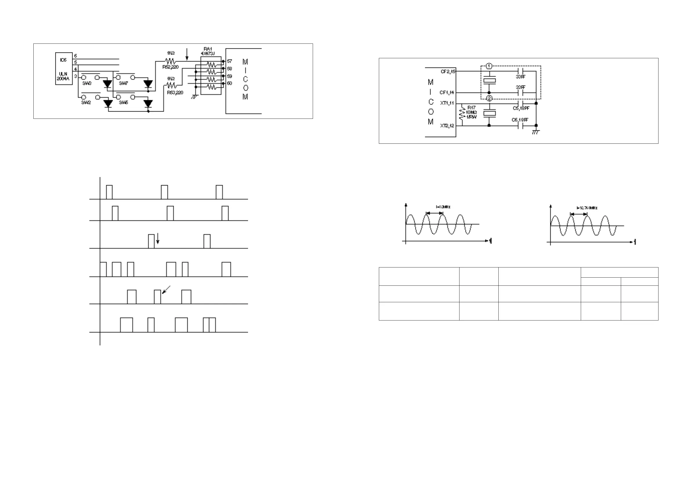
• Part of the button scan
The system of the BUTTON SCAN is in wide use for the method of the DUTY output part in L.E.D DRIVE,
yet here, it is in use for the method of the segmental output.
• Though the period of the DUTY part is 1/9, the last 9th part does not generate the waveform and checks
the button input with getting out the segmental output at the same time.
• The RA1(473J, 47KΩ) is a ‘PULL DOWN’ resistance for preventing floating action.
• The D15 prevents the L.E.D from turning on unnecessarily with forming the closed loop like a threaden
line at the time of button push.
Duty Part
Segment Part
Waveform
No Generation
Segmental Waveform
for Button Input