45 46
• The element which has an effect on data of LOAD SENSOR
DISPLAY UNIT
1. CIRCUIT DIAGRAM
CONDITION SPECIFICATION
VOLTAGE
CAPACITY OF CONDENSER
TENSION OF BELT
SAFETY SWITCH UNIT
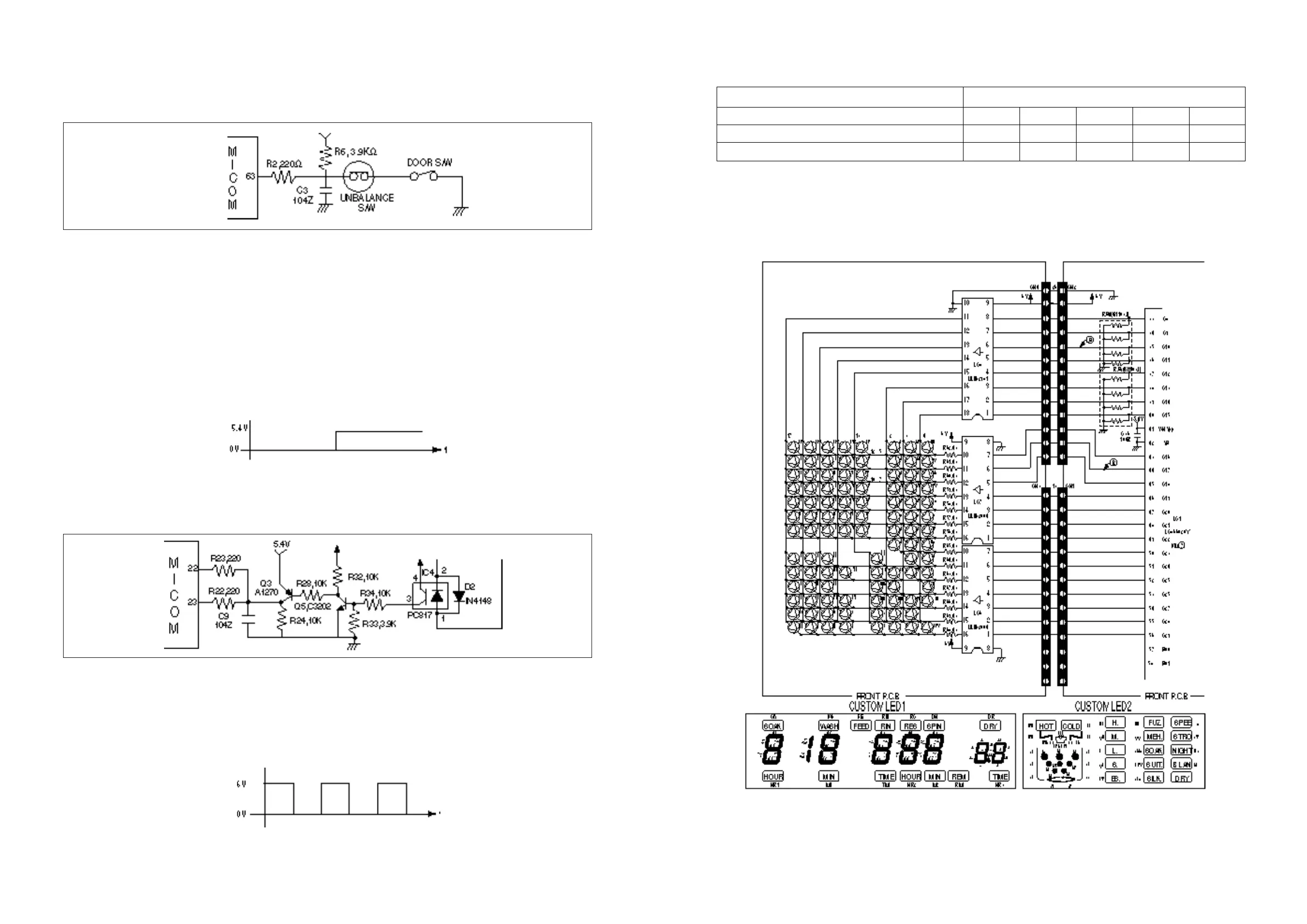
1. CIRCUIT DIAGRAM
2. EXPLANATION OF CIRCUIT
• The MICOM terminal No. 63 gets into ‘ L’ at the state of the closed lid. If lid is open in spinning state,
the MICOM generates error signal as ‘ LE’.
• Case of range 40mSEC~300mSEC in spinning time: It is regarded that washing clothes should be
inclined. Accordingly washing time increases 8 minutes and rinsing action takes place another one time.
Case of above 300 mSEC : It is regarded that lid should be open. Therefore it is displayed as ‘LE’.
3. CAUTION FOR A/S
• Be level with the ground.
• The ‘UE’ error occurs in case of not being level with the ground.
• The waveform between the MICOM terminal No. 63 and the GND.
LOAD SENSOR UNIT
1. CIRCUIT DIAGRAM
2. EXPLANATION OF CIRCUIT
• Detecting the voltage of running condenser, it sends the sensing data to the MICOM terminal No. 22 &
23. That is, as charging & discharging time of runing condenser becames different according to the
loads, in fuzzy course the washing time is determined by sensing the quantity of washing clothes.
• The waveform between the part of 1 and the GND(waveform of pulse).
Lid is closed Lid is open
100V AC 110V AC 127V AC 220V AC 240V AC
65.0 µF 54.0 µF 41.6 µF 13.5 µF 11.4 µF
450gf 450gf 450gf 450gf 450gf