Do you have a question about the Daewoo DWF-4220 Series and is the answer not in the manual?
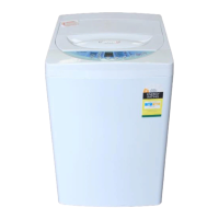
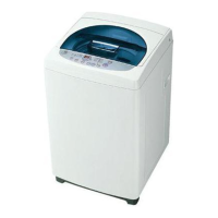
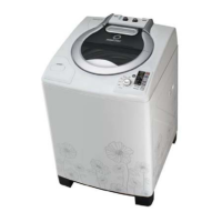
Introduction to the service manual for the specific washing machine models.
Details on electrical power requirements and energy usage.
Physical size (width, height, depth) and weight of the unit.
Available washing cycles and water level selections.
Details on pulsator, motor, filters, and other components.
Key features including air bubble system, low-noise design, and one-touch operation.
Explanation of how water currents are used to adjust unbalanced loads during operation.
How the pulsator generates water currents for washing.
System for automatically adjusting drain time based on conditions.
How the dispenser works using centrifugal force during spin cycles.
Visual and descriptive explanation of softener movement through the dispenser.
Prevention of abnormal vibration during spin cycles via a safety switch.
System for circulating water to improve washing/rinsing and the function of the lint filter.
Instructions for cleaning the lint filter to remove accumulated lint.
Explanation of the synchronous motor's components and operating principles.
Details on the gear mechanism's role in creating water currents and preventing clothing damage.
Explanation of the structure and function of the bubble generator.
How air is managed by the armature and bellows in the bubble system.
How the trans core and magnet interact for air system operation.
Explanation of air bubble creation and dispersion within the washing tub.
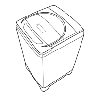
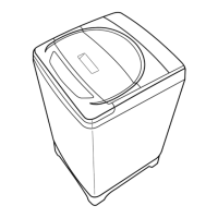
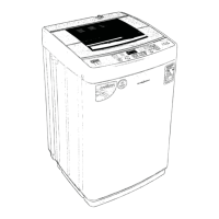
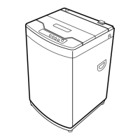
Labels for key parts of the washing machine structure like tub, panel, and inlets.
List of accessories provided with the washing machine, such as hoses and adapters.
Description of the control panel's micom sensor and indicator lamps.
Detailed explanation of each button's purpose on the control panel.
Recommendations and warnings for choosing a suitable installation place.
Steps for setting the height and checking the horizontal status of the machine.
Guidelines for installing the drain hose correctly to prevent issues.
Step-by-step instructions for connecting the drain hose to the machine and standpipe.
Notes on proper hose height, length, and preventing siphoning.
Detailed steps for attaching the inlet hose to standard and screw-shaped water taps.
Instructions for connecting the hose to the washing machine's water inlet.
Guidelines for connecting the ground wire to earth or water taps.
Warnings against connecting the ground wire to gas pipes or telephone wires.
How to select courses like Fuzzy, Speed, Heavy, Wool and set water levels.
Steps to take after washing is finished, including tap closure and cleaning.
How to select individual wash, rinse, or spin processes or combinations.
Step-by-step guide for removing and replacing the gear mechanism assembly.
Procedures for replacing the synchronous motor and drain valve components.
Steps for adjusting the brake lever for proper brake performance.
Diagnostic steps and solutions for issues related to the washer not receiving water.
Troubleshooting steps when the indicator lamp does not light up when the power is pressed.
Solutions for issues like progress lamps not lighting up or motor not rotating.
Diagnostic flowcharts and solutions for draining problems.
Troubleshooting steps for when the washing machine fails to spin.
Identifying and resolving causes of abnormal noise during the wash cycle.
Covers issues with indicator lamps, motor operation, and abnormal noise during washing.
Table detailing error messages, their causes, and corresponding solutions.
How to operate the test mode and interpret the displayed information.
Block diagram showing the interaction between various units like display, input, and load drive.
Detailed explanation of each pin on the MICOM IC (42 DIP).
Circuit diagram for controlling loads like motors, valves, and bubble generators.
Detailed explanation of the circuit's operation during CW wash, including TRIAC control.
Precautions and checks for TRIAC components and their related circuits.
Circuit diagram for the water level sensor unit.
Explanation of how water level is detected and its relation to frequency.
How different water levels correspond to specific frequencies.
Precautions for A/S regarding water level sensing and potential error messages.
Circuit diagram for the electric power supply unit, showing transformer and regulator.
Explanation of the power supply circuit's components and voltage measurements.
Cautions for A/S related to checking condensers and voltage in the power supply unit.
Circuit diagram and explanation of the reset unit for program initialization.
Cautions for A/S regarding the reset unit's output and input.
Circuit diagram and explanation of the buzzer unit's activation.
Circuit diagram showing how button inputs are processed.
Circuit diagram and specifications for the crystal oscillator unit.
Circuit diagram for the safety switch unit.
Circuit diagram for the load sensor unit.
Explanation of how the load sensor detects running condenser voltage and determines washing time.
Circuit diagram illustrating the display unit and its connection to various controls.
Detailed wiring diagram for the pump model of the washing machine.
Detailed wiring diagram for the non-pump model of the washing machine.
List of parts related to the assembly plate.
List of parts associated with the washing machine tub.
List of parts for the tub, motor condenser, and pulley motor.
List of parts related to the gear mechanism and its protector.
List of parts for the washing machine cabinet and base assembly.
List of parts for the shaded pole motor.
List of parts for filters, packing, washers, and accessories.
List of parts for washing machine assemblies like suspension and cover.
Diagram showing the layout of control panel and front-facing components.
Diagram illustrating internal components accessed from the front.
Exploded view diagram of the tub assembly and its related parts.
Diagram showing specific components for the non-pump model.
List of P.C.B. resistors with values from 3.9kΩ to 330Ω.
List of P.C.B. resistors, including carbon film and M-Oxide film types.
List of resistor arrays and ceramic capacitors for the P.C.B.
List of ceramic and electrolytic capacitors used on the P.C.B.
List of diodes and transistors used on the P.C.B.
Detailed list of various capacitor types and their specifications.
List of diodes and transistors, including specific part numbers.
List of transistors, MICOM IC, audio reset IC, and regulator IC.
List of connectors, screws, and TRIAC components used on the P.C.B.
Complete circuit diagram for the pump model washing machine.
Complete circuit diagram for the non-pump model washing machine.
Diagrams showing the layout of the top and bottom sides of the bare P.C.B.