Do you have a question about the Daewoo FR-700NB and is the answer not in the manual?
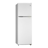
Provides dimensional specifications for different refrigerator models.
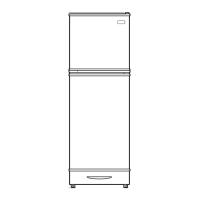
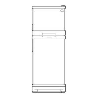
Identifies and labels all external components of the refrigerator.
General outline including model, capacity, dimensions, and weight.
Details of electrical components like compressors for different models and voltages.
Specifications for starting capacitors based on refrigerant and voltage.
Specifications for running capacitors based on refrigerant and voltage.
Details of F-FAN, R-FAN, and C-FAN motors, including type, part code, and speed.
Specifications for the defrost heater, including voltage and part code.
Specifications for the lamp assembly, including voltage and part code.
Specifications for the PCB transformer, including type name and part code.
Specifications for the main PCB assembly, including type name and part code.
Specifications for the dryer, including capacity and part code.
Specifications for PCB fuse, thermo fuse, door switch, F-sensor, and R-sensor.
Details various power cord types, part codes, and their usage regions.
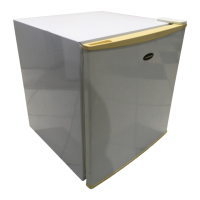
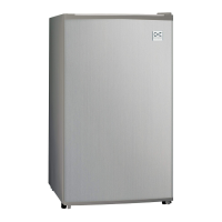
Details the available door color options for freezer and refrigerator doors.
Explains the normal state and LED indicators for the refrigerator display.
Describes temperature regulation for the freezer compartment using the FRZ.SET button.
Describes temperature regulation for the refrigerator compartment using the REF.SET button.
Details how to activate and manage the SILENT mode using the SILENT button.
Explains temperature control for the freezer compartment via FRZ.SET and fan operation.
Explains temperature control for the refrigerator compartment via REF.SET and fan operation.
Details the terms and conditions for starting and finishing SILENT Mode.
Explains defrosting period conditions and operation modes: Pre-cool, Heater, Pause, Fan-delay.
Describes error code display, meaning, control, and dissolution for various refrigerator errors.
Details the process for initiating and performing forced defrosting.
Explains time delays for fan operation related to compressor status or door openings.
Describes the initial defrosting process that occurs upon initial power supply.
Explains initial operations and display functions after the refrigerator is delivered.
Details the mechanism that prevents the compressor from restarting immediately after shutdown.
Explains the various conditions that trigger the buzzer alarm in the refrigerator.
Describes how to activate and utilize the demonstration mode for product display.
Explains how the R-Sensor off-points are controlled under different operating conditions.
Provides a detailed schematic of the refrigerator's electrical circuit layout.
Illustrates the air circulation paths within the refrigerator and freezer compartments.
Shows the flow and components of the refrigerant cycle within the cooling system.
Step-by-step guide for removing and disassembling the refrigerator and freezer doors.
Instructions for disassembling and removing the refrigerator door handles.
Steps for removing and replacing the freezer compartment light bulb.
Guide for removing the F Louver A and F Louver B components.
Instructions for replacing F and D sensors, including wire connections.
Steps for removing fan motors and distinguishing between F and R fan motors.
Steps for removing and replacing the defrosting sensor on the evaporator.
Steps for removing and replacing the temperature fuse from its fixing clip.
Guide for removing the evaporator, including pipe disconnection and protection.
Steps for replacing the defrost heater, involving connector removal and evaporator movement.
Instructions for removing the refrigerator compartment light bulb cover and the bulb itself.
Steps for removing the top panel of the refrigerator unit.
Instructions for removing the return duct cover and its associated components.
Guide for removing the cubic duct and the side louver components.
Steps for removing the check valve and the R Sensor from the unit.
Detailed steps for disassembling and removing the front control panel.
Comprehensive guide for removing the compressor, including relay, pipes, and washers.
Steps for removing wire-condenser pipes, dryer fixing cable, and fan cover.
Instructions for removing the return duct cover.
Visual diagrams illustrating the exploded view of various refrigerator components.
Comprehensive list of all parts with part codes, names, descriptions, and quantities.
Visual diagram and list of parts specifically related to the machine room assembly.
| Model | FR-700NB |
|---|---|
| Category | Refrigerator |
| Type | Top Freezer |
| Cooling System | Static |
| Defrost Type | Manual |
| Energy Star Certified | No |
| Color | White |
| Energy efficiency class | A+ |